Table of Contents
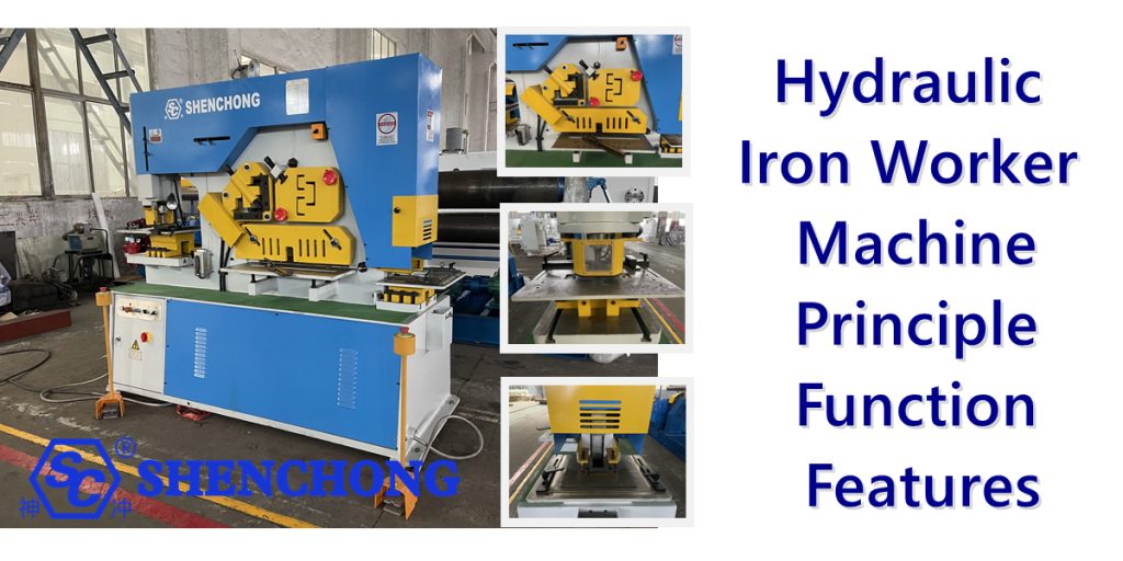
The hydraulic iron worker machine is a multi-purpose metalworking machine that combines punching, shearing, bending, notching, and angle cutting. It is widely used in industries such as steel structures, bridges, automobile manufacturing, machining, and power distribution cabinets. The following is a detailed introduction to its functions and features.
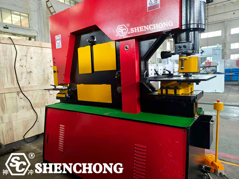
1. Hydraulic Iron Worker Machine Overview
A hydraulic ironworker combined punching and shearing machine is a multifunctional hydraulic device that integrates multiple metalworking processes, including punching, shearing, bending, notching, and corner trimming, into a single machine. It utilizes hydraulic power to drive multiple working mechanisms, enabling rapid completion of various steel processing tasks.
This equipment is widely used in:
- Steel structure manufacturing
- Bridge construction
- Power equipment
- Sheet metal processing
- Automotive manufacturing
- Metal products and assembly industries
Structural Components:
A hydraulic combined punching and shearing machine primarily consists of the following components:
Hydraulic System
Utilizes a high-performance hydraulic pump and valve block to provide stable pressure and flow.
Overload protection and pressure regulation ensure safe operation.
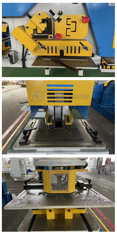
Punching Station
Used for producing round, long, and square holes in steel plates, angle steel, and channel steel.
A variety of hole shapes can be achieved by changing dies.
Shearing Station
Includes various blade options, including flat shears, angle shears, round steel shears, and channel steel shears.
Sheared surfaces are smooth and burr-free.
Angle Cutting Station
Capable of performing right-angle or bevel cuts, as well as V-grooving in panels.
Operation Control System
A foot pedal and dual operating console design allow two people to operate independently.
The electronic control system is equipped with emergency stop and safety limit switches.
2. Working Principle of iron workers
A hydraulic iron worker machine uses a hydraulic system as its power source. Hydraulic oil pumped through an oil pump drives a hydraulic cylinder, which in turn drives the upper tool holder or punch head in reciprocating motion, thereby performing processing operations such as punching, shearing, bending, and corner trimming on metal materials.
In short, its core principle is:
The motor drives the hydraulic pump, which generates high-pressure hydraulic oil, which then drives the hydraulic cylinder, which then performs the punching and shearing operations through a mechanical transmission structure.
1) Working Principle of the Hydraulic System
Power Section
The electric motor drives the hydraulic pump, which draws in and pressurizes the hydraulic oil, creating a high-pressure oil flow.
Control Section
The hydraulic oil flows through control components such as relief valves, reversing valves, and throttle valves to regulate the system’s pressure, flow rate, and direction.
Different workstations (such as punching and shearing) operate independently or alternately via reversing valves.
Execution Section
When the operator depresses a foot switch or pushes a button, a solenoid reversing valve activates, directing high-pressure oil into one side of the hydraulic cylinder. The hydraulic cylinder’s piston rod pushes the upper tool holder or punch downward, completing the punching and shearing process.
When the operating button is released, the reversing valve resets, the hydraulic oil flow changes, and the piston rod returns in the opposite direction, completing one cycle.
2) Operation principle of main working mechanism
Workstations | Principle | Method |
Punching station | A hydraulic cylinder pushes downward, and the punch punches through the die to create a hole in the work piece. | The die is fixed between the worktable and the slide, and the hydraulic cylinder reciprocates to complete the punching process. |
Shearing station | The upper tool carrier is pushed downward by a hydraulic cylinder, and the sheet metal is sheared between the upper and lower blades. | The shear gap is adjustable to accommodate sheet metal of varying thicknesses. |
Angle cutting station | A hydraulic cylinder drives the shear mechanism downward, creating corner cuts. | Equipped with either a right-angle or adjustable-angle tool. |
Profile cutting station | Specialized blades shear round steel, square steel, angle steel, and other profiles. | The upper and lower blades coordinate to ensure a smooth cut surface. |
Bending station | A small hydraulic cylinder or main cylinder drives the bending die downward, and the sheet metal is bent and formed. | Suitable for rapid bending of small sheet metal parts. |
3) Hydraulic Power Transmission Process (Schematic Illustration)
- Oil Tank: Stores hydraulic oil and filters impurities through a filter.
- Hydraulic Pump: Driven by an electric motor, pressurizes the hydraulic oil.
- Relief Valve: Maintains stable system pressure to prevent overload.
- Directional Valve: Controls the direction of oil flow, determining the direction of movement of the hydraulic cylinder.
- Throttle Valve: Adjusts the oil flow rate to control operating speed.
- Hydraulic Cylinder: Actuator, converts hydraulic energy into mechanical energy.
- Tool Holder/Punch: Driven by a hydraulic cylinder to perform the specific shearing or punching action.
4) System Features
Smooth power transmission with minimal impact
The hydraulic system offers excellent cushioning performance and gentle operation, preventing impact damage to the mold or machine body.
Adjustable pressure for a wide range of applications
The hydraulic system’s operating pressure can be adjusted to suit different plate thicknesses and materials.
Multi-station independent control
Each workstation has an independent hydraulic control circuit, enabling independent or simultaneous operation for improved efficiency.
Safe and reliable
Equipped with a pressure relay, relief valve, and limit devices to prevent overloading and misoperation.
5) Working Cycle Example (using punching as an example):
- Start the motor → Hydraulic pump operates → System pressure builds.
- Operator depresses the foot switch → Solenoid valve activates → Oil flows into the lower chamber of the punching cylinder.
- Piston descends → Punch passes through the die, completing the punching.
- Release the foot switch → Reversing valve resets → Oil flows into the upper chamber of the cylinder → Piston returns to its original position.
- The cycle ends, and the operator waits for the next operation.
6) Typical Model Parameters (Q35Y series as an example)
Model | Maximum punching force (kN) | Maximum punching diameter x thickness (mm) | Sheet Thickness × Width (mm) | Cutting thickness (mm) | Motor power (kW) | Weight (kg) |
Q35Y-16 | 600 | Ø26 x 16 | 250 × 16 | 8 | 5.5 | 1600 |
Q35Y-20 | 900 | Ø30 x 20 | 330 × 20 | 10 | 7.5 | 2300 |
Q35Y-25 | 1200 | Ø35 x 25 | 355 × 25 | 12 | 11 | 3000 |
Q35Y-30 | 1600 | Ø38 x 30 | 410 × 30 | 14 | 11 | 4200 |
3. Main Functions Of iron worker punching and cutting machine
- Punching
Applicable for punching round, square, and oblong holes in steel plates, angle steel, and channel steel.
Replace the die to create holes of varying shapes and sizes.
High punching efficiency, excellent precision, and smooth edges.
- Shearing
Applicable for shearing ordinary steel plates and stainless steel plates.
Shearing surfaces are smooth and burr-free.
Common specifications such as Q35Y-20 can shear steel plates with a maximum thickness of approximately 16mm.
- Angle Cutting
Applicable for right-angle, bevel, and V-shaped shearing.
Suitable for cutting or shaping the corners of angle steel and channel steel.
- Profile Cutting
Applicable for shearing various profiles, including round steel, square steel, flat steel, angle steel, and channel steel.
Equipped with a dedicated profile shearing blade, the shearing surface is clean and consistent.
- Bending
Equipped with a small bending die, simple sheet metal bending can be performed. Suitable for rapid prototyping of small sheet metal parts.
- Notching
Used for creating notches in square tubes or sheets to facilitate subsequent welding and assembly.
4. Equipment Features and Advantages
- Multifunctional Integrated Design
One machine performs multiple functions, saving equipment investment and space.
Easy die changes enable quick switching between various processing steps.
- Hydraulic Drive System
Stable and reliable, with low noise and minimal impact.
Powerful power, suitable for processing thick plates and high-strength steel.
- Efficient Operating System
Equipped with dual operating tables, two people can operate different workstations simultaneously, improving efficiency.
Features both foot-operated and manual control modes for flexibility and safety.
- High-Precision Processing
Shearing and punching provide high precision and repeatable positioning.
Sheared surfaces are smooth and free of visible burrs.
- Safety Devices
Equipped with limit switches, emergency stop, and protective guards to ensure safe operation.
- Easy-Maintenance Structure
The hydraulic system is simple and reliable, ensuring easy maintenance.
Standardized, versatile wearing parts facilitate easy replacement.
- Durable and Sturdy
The entire machine is welded from high-quality steel plates, heat-treated, and stress-relieved to ensure long-term, stable operation.