Table of Contents
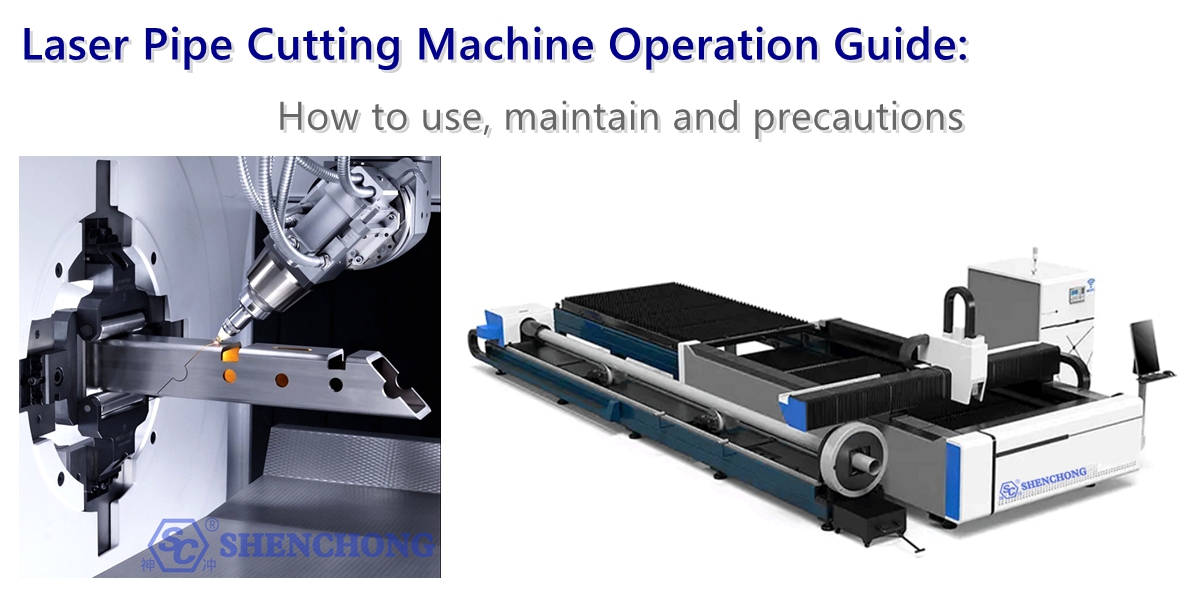
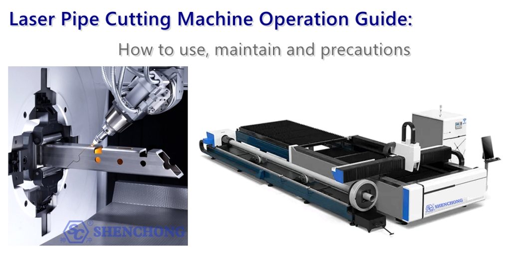
Laser pipe cutting machines, through automation and laser technology, enable a single machine to complete all processes such as cutting, drilling, and grooving, improving efficiency and processing precision. This significantly increases production efficiency, reduces costs, improves material utilization, supports flexible production, and comprehensively enhances a company’s competitiveness.
Below is an operation guide for laser tube cutting machines, including operating procedures, key parameters, maintenance, common problems, and safety precautions. It is suitable for training, on-site operation, and customer use.
1. Tube Laser Cutting Equipment Composition and Basic Understanding
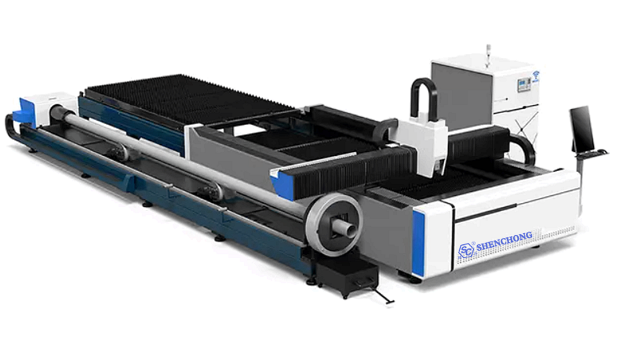
A typical laser pipe cutting machine consists of the following systems:
1) Core System
- Laser (primarily fiber laser)
- Cutting head (auto-focusing)
- CNC system (e.g., TubePro/FSCUT)
- Machine Frame
2) Motion and Clamping System
- Front and rear chucks (auto-clamping)
- Follow-up support (prevents tube sagging)
- X/Y/Z axis + rotary axis (enabling rotary cutting of the tube)
3) Auxiliary Systems
- Cooling water system
- Dust removal system
- Air compressor / gas system (oxygen / nitrogen / air)
- Automatic feeding system (optional)
2. The Most Important Preparations Before Cutting Pipes
1) Accurate Material Confirmation
Before cutting pipes, the following must be confirmed:
- Material: Carbon steel, stainless steel, aluminum alloy, copper, galvanized pipe, etc.
- Wall Thickness: Thin-walled pipe, standard wall thickness, thick-walled pipe
- Specifications: Outer diameter, inner diameter, length, ovality
- Pipe Type: Round pipe, square pipe, rectangular pipe, elliptical pipe, channel steel, special-shaped pipe
- Surface Condition: Whether there is oil, rust, coating, or oxide film
Different materials have different requirements for laser absorption rate, melting state, and spatter. For example, stainless steel usually prioritizes the smoothness of the cut, carbon steel focuses more on efficiency and slag control, while aluminum and copper are more dependent on power, auxiliary gas, and reflection safety.
2) The pipe itself must be sufficiently "regular"
Many cutting problems are not equipment issues, but rather problems with the pipe itself:
- Excessive ovality in round pipes
- Large side length error in square pipes
- Bending in pipes
- Uneven pipe ends
- Obvious weld protrusions
- Heavy oxide scale or oil stains on the surface
These can lead to:
- Instable clamping
- Automatic edge finding error
- Cut offset
- Abnormal perforation
- Poor dynamic balance during rotation
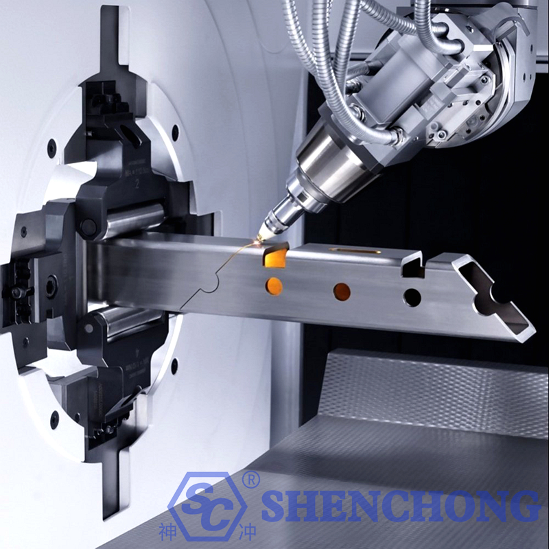
3) Clamping and support must be reliable
During pipe cutting, the pipe generally needs to be stabilized by a chuck, material support, and follow-up support.
Note:
- Clamping should not be too loose, otherwise it will cause vibration, eccentricity, and asynchronous rotation during cutting.
- Clamping should not be too tight, otherwise it will damage thin-walled pipes or deform the pipe. Long pipes must have sufficient support to prevent sagging in the middle section.
- When cutting to the end, if the remaining material is too short, it is prone to shaking and requires special attention.
4) Drawings and layout must be checked first
Many batch reworks stem from problems in the initial programming.
Before cutting the pipe, confirm the following:
- Are the dimensions on the drawing complete?
- Are the opening positions correct?
- Is the beveling angle correct?
- Are reasonable gaps reserved at the splicing joints?
- Are the node holes, welding holes, and positioning holes suitable for subsequent assembly?
For laser-cut pipes, “being able to cut” does not mean “being able to assemble.” Subsequent assembly tolerances must be considered in advance.
3. Laser Pipe Cutting Machine Operation Procedures (Standard Steps)
1) Pre-Start Inspection
- Check gas pressure (oxygen/nitrogen/air)
- Check chiller water temperature (generally 20–25℃)
- Check lubrication status
- Check chuck functionality
Important:
The laser must be powered on with water before starting.
Confirm no air leaks and no alarms.
2) Startup Sequence
- Turn on main power
- Start chiller
- Start air compressor/gas system
- Start control system (CNC)
- Turn on laser
Incorrect sequence is strictly prohibited, otherwise the laser will be damaged.
3) Loading and Positioning
- Place the pipe into the chuck
- Automatic/manual clamping
- Set pipe type (round/square/irregular shape)
- Perform alignment (centering)
Key Points:
The pipe should not be bent excessively. Long pipes must have the follow-up support activated.
4) Program Import and Layout
- Import drawings (usually CAD/Tekla/SolidWorks)
- Automatically generate cutting paths
- Set cutting sequence (reduce deformation)
Recommendation:
- Prioritize cutting small holes. → Re-cut the contour
- Avoid continuous heat concentration
5) Parameter Settings (Core)
Common Parameters:
- Laser Power
- Cutting Speed
- Gas Type and Pressure
- Focus Position
Parameter Examples (Reference):
Material | Thickness | Gas | Power | Features |
Carbon steel | 3mm | Oxygen | Medium | Fast cutting |
Stainless steel | 3mm | Nitrogen | High | Oxidation-free |
Aluminum | 2mm | Nitrogen | High | Anti-reflective |
6) Start Cutting
- Dry Run to Check Trajectory
- Low Power Trial Cut
- Formal Cut
Laser Pipe Cutting Machine Key Operating Points:
- Observe Spark Status in Real Time
- Check for Chuck Looseness
- Listen for Abnormal Sounds
7) Unloading
- Release Chuck After Cutting
- Clean Up Residual Material
- Sort and Stack Material
4. Key Techniques for Laser Tube Cutting
1) Proper Focal Point Selection
The focal point directly affects the kerf width, slag buildup, heat-affected zone, and cut perpendicularity.
Generally speaking:
Thin-walled tubes: Prefer smaller focal points and higher speeds to reduce heat input.
- Thick-walled tubes: Require more stable energy concentration to ensure penetration and slag removal.
- Stainless steel: Often aims for a smoother cross-section and less oxidation.
- Carbon steel: Commonly uses oxygen-assisted cutting to increase speed, but requires control of oxidation edges.
Incorrect focal point adjustment commonly manifests as:
- Large upper opening, small lower opening
- Severe slag buildup at the lower opening
- Blackened or yellowed cut surface
- Excessively long piercing time
- A noticeable taper in the cross-section
Empirically, the focal point is not a fixed value but should be dynamically adjusted based on tube diameter, wall thickness, material, and gas conditions.
2) Cutting speed must match power
Too slow:
Excessive heat input, wider kerf, pipe deformation, severe surface ablation, increased slag buildup at the lower edge.
Too fast:
Incomplete cut, intermittent cutting, edge stringing, tail residue, magnified hole position deviation. The correct approach is not to blindly pursue “faster,” but to find a stable window.
Especially in:
Small round pipes, thin-walled stainless steel pipes, corners of irregularly shaped pipes, complex shapes with holes or grooves. These locations are more prone to localized quality degradation due to inappropriate speed.
3) Assist gas selection is crucial
The assist gas affects not only slag removal but also oxidation, kerf color, and cutting speed.
- Oxygen
Suitable for thick carbon steel plates/pipes; exothermic reaction, high cutting efficiency, but the kerf will oxidize, resulting in a darker edge color.
Advantages:
- High speed
- Suitable for thicker carbon steel
- Good penetration
Disadvantages:
- Significant oxidation at the cut
- Large heat-affected zone
- Subsequent welding and painting may require oxide layer treatment
- Nitrogen
Commonly used for stainless steel, aluminum alloys, and other applications requiring high cut quality.
Advantages:
- Smooth cut
- Less oxidation
- Good surface quality
- Easier subsequent processing
Disadvantages:
- High requirements for gas pressure and purity
- Relatively higher cost
- Cutting speed may decrease for thick-walled materials
- Air
Suitable for some low-cost, low-requirement applications, or economical processing of thin materials.
Advantages:
- Low cost
- High convenience
Disadvantages:
- Generally lower cut quality
- Significant oxidation
- Not ideal for high-requirement parts
4) Drilling method should be optimized according to wall thickness
In pipe cutting, drilling is a crucial step. Poor drilling directly affects the subsequent cutting quality.
Common Techniques:
- Thin-walled tubes should be pierced quickly to reduce heat accumulation.
- Thick-walled tubes should be pierced in stages to avoid slag splashing.
- Complex shapes should avoid piercing along critical structural edges.
- Highly reflective materials require special attention to the risks of reflection and backlighting.
Unstable piercing can easily lead to:
- Overheating at the starting cut point
- Collapse at the hole edge
- Slag splashing contaminating the lens
- Gap at the cut start
5) Proper Cutting Path Planning
Path planning is crucial, especially for complex parts with holes, slots, openings, bevels, and spliced ends.
Principles of Path Planning:
- Cut internal features first, then the outer contour.
- Cut small holes first, then large holes.
- Cut stable areas first, then easily deformable areas.
- Residual material becomes increasingly unstable towards the end; the path should consider supporting the remaining material.
- Avoid cutting supports at weak structural points first.
For square, rectangular, and irregularly shaped tubes, special attention should be paid to heat accumulation at corners and deceleration at corners during path planning. Otherwise, burn-through at corners or excessively rounded corners may occur.
6) Slow Down at Corners and Inflection Points
Corners are one of the most problematic areas in pipe cutting.
This is because when the laser head turns:
- Speedchanges
- Energy distribution changes
- Molten pool state changes
- Mechanical system acceleration/deceleration changes
Without corner control, common problems include:
- Overheating at corners
- Excessive fillet radius
- Dimensional deviations
- Cut jiggling
- Slag buildup at corners
Therefore, appropriate settings should be made based on the drawing:
- Corner slowdown
- Inflection point power compensation
- Small fillet transition
- Optimized tool entry/exit
7) Special Handling of Pipe End Residue and Tail Material
Many pipe cutting accidents occur in the final section of residual material.
The reasons are:
- Shorter pipes result in decreased rigidity.
- The clamping center changes.
- The remaining material is lighter, leading to unstable rotational inertia.
- It is prone to colliding with the chuck, support, or cutting head.
Therefore, it is necessary to plan ahead for:
The length of the remaining material; the method of recovering the remaining material; the speed and clamping strategy for the last few cuts; and whether a special program for the remaining material is needed.
8) The height of the follow-up support must be properly adjusted
Long pipes, heavy pipes, and large-diameter pipes especially require follow-up supports. Incorrect support height will cause:
- Pipe sagging
- Cut deviation
- Rotational runout
- Hole position error
- Surface scratches
If the support is too high, it may not be stable. If it is too low, it may bend the pipe. Ideally, the pipe should roll or rotate smoothly during the cutting process, without significant suspension or pressure.
5. Key Considerations for Cutting Different Pipe Materials
1) Round Pipes
Round pipes are the most common type.
Key considerations:
- Coaxiality of rotation
- Center clamping alignment
- Roundness error
- Positioning accuracy during hole drilling
Common problems with round pipes:
- Hole offset around the circumference
- Non-perpendicularity of the cut end face
- Instable cutting at weld seams
- Deformation of small-diameter pipes
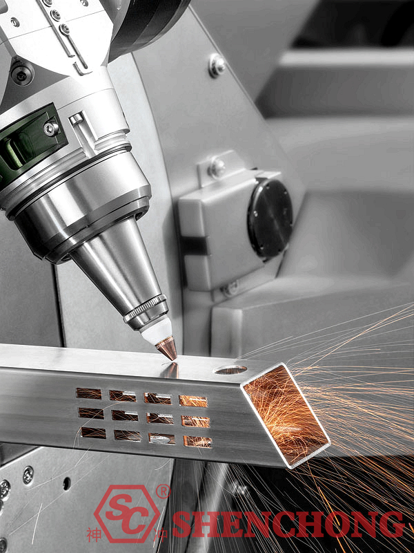
2) Square/Rectangular Pipes
Key considerations:
- Heat accumulation at corners
- Corner dimensional accuracy
- Flatness of clamping surface
- Reasonableness of the cutting head’s corner path
Corners of square pipes are often more prone to overheating or slag buildup than edges because heat is more concentrated at corners, and the cutting trajectory is more complex.
3) Thin-Walled Pipes
The key to cutting thin-walled pipes is “less heat input.”
Notes:
- Fast but stable cutting speed
- More sensitive to focal point and air pressure
- Clamping force should not be excessive
- Support should not damage the pipe wall
- Small holes and narrow grooves are prone to deformation
4) Thick-Walled Pipes
The key to cutting thick-walled pipes is “ensuring penetration and slag removal.”
Note:
- Sufficient power and gas pressure are required.
- Sufficient piercing time is necessary.
- Speedshould not be blindly too fast.
- Lens protection is paramount.
- The risk of slag backflow is higher.
5) Highly reflective material tubing
For materials such as aluminum, copper, and many coated materials, note:
- Reflection risk
- Narrow process window
- High requirements for lens and cutting head protection
- Parameters need to be more carefully considered.
6. Maintenance (Key Points)
Daily Maintenance:
- Clean the cutting head lens
- Check nozzle for damage
- Clean up worktable debris
- Check air pressure and water temperature
Weekly Maintenance:
- Check guide rail lubrication
- Check chuck clamping accuracy
- Clean the dust collector
Monthly Maintenance:
- Calibrate the optical path
- Check laser status
- Replace filters (gas/water)
List of Vulnerable Parts:
- Nozzle
- Protective lens
- Sealing ring
- Filter element
It is recommended to maintain a spare parts inventory.
7. Pipe Laser Cutting Common Problems and Solutions
1) Incomplete Cut
Causes:
- Insufficient power
- Incorrect focus
- Insufficient air pressure
Solutions:
- Increase power / Decrease speed
- Refocus
2) Severe Burrs
Causes:
- Excessive speed
- Low gas purity
- Damaged nozzle
Solutions:
- Adjust parameters
- Replace gas / Nozzle
3) Blackened Cut (Stainless Steel)
Causes:
- Using oxygen
- Insufficient nitrogen pressure
Solutions:
- Use high-pressure nitrogen
4) Tubing Vibration
Causes:
- Insufficient support
- Loose chuck
Solutions:
- Enable follow-up support
- Check clamping force
8. Safety Precautions
Laser tube cutting is a high-power, high-speed, high-intensity light, and high-airflow device; safety is paramount.
1) Protective goggles and safety doors must be in place
The laser must not be observed directly; protective measures must be taken according to equipment requirements.
2) Be aware of reflection risks
Especially when cutting highly reflective materials such as aluminum, copper, and brass, reflected light may damage the equipment.
3) Strict fire prevention
Sparks, molten slag, and hot splashes will occur during tube cutting.
The following should be taken on-site:
- Clean up flammable materials
- Equip fire extinguishing equipment
- Monitor slag buildup at the cutting end
- Prevent oil accumulation
4) Risk of mechanical pinching
The chuck, support, and feeding mechanism all pose a risk of pinching. Power must be strictly disconnected or operations must be performed according to regulations when adjusting the machine and changing materials.
5) High-pressure gas safety
Gas cylinders, pipelines, and pressure reducing valves must be inspected regularly to prevent leaks and pressure runaway.
9. Summary
In traditional pipe processing, multiple processes such as sawing, punching, and drilling are performed separately, resulting in low efficiency, inconsistent accuracy, and heavy reliance on manual experience.
Facing the current manufacturing demands for high precision, fast delivery, and flexible production, traditional equipment can no longer support the large-scale and standardized development of enterprises.
Pipe laser cutting machines integrate high-performance fiber laser technology with intelligent CNC systems, achieving integrated automated processing from loading, positioning, cutting to unloading.
Laser Pipe Cutting Machine Operating Procedure:
Inspection → Start-up → Clamping → Parameter Adjustment → Trial Cut → Forward Cut → Shutdown
Tube Laser Cutting Key Usage Points:
- Cool before laser (protect the laser)
- Chuck clamping + concentric alignment (ensure accuracy)
- Match parameters to materials (power/speed/gas)
- Trial cut is mandatory (avoid batch scrap)
- Do not leave the operator during cutting (prevent accidents)
- Follow the correct shutdown sequence (extend machine life)