
Table of Contents
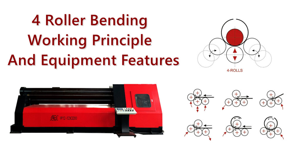
4 roller bending process is a widely used method for forming metal plates. It utilizes the rotation of the machine’s rollers, the clamping of the metal plate, and the vertical movement of the side rollers to induce gradual plastic deformation in a flat plate, ultimately shaping it into cylinders, arcs, conical sections, or other curved components.
Compared to traditional three-roll bending machines, the four-roll bending machine offers several distinct advantages: it requires only a single setup, allows for pre-bending of both ends, enables continuous rolling, features a higher degree of automation, and provides superior control over the roundness of the workpiece and the repeatability of the forming process.
1. Basic Concepts of 4 Roller Bending Process
The 4 roller bending process employs four working rollers—each with a specific function—to apply clamping force, frictional driving force, and bending moments to a metal plate. This transforms the plate from a flat state into an arc or cylinder with a defined curvature.
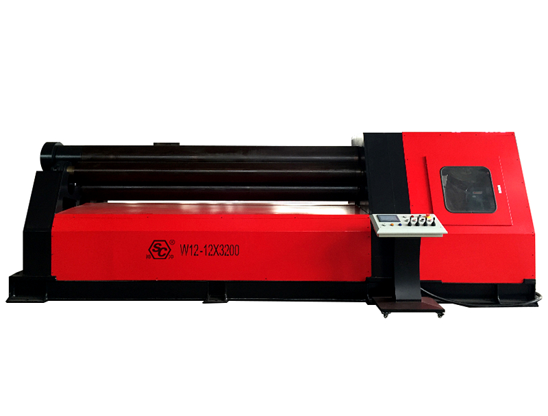
A four-roll bending machine typically consists of an upper roller, a lower roller, left and right side rollers, a hydraulic drive system, a main transmission system, a machine frame, a numerical control (CNC) system, and safety protection devices.
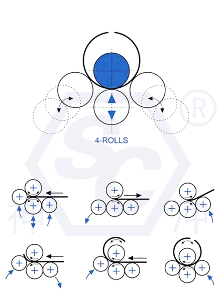
1) Configuration of a typical four-roll plate bending machine
Main Components | Functions and Roles |
Upper Roll | Serves as the primary forming support and works in conjunction with the lower roll to clamp the metal sheet |
Lower Roll | Applies upward pressure to clamp the sheet and, in coordination with the drive system, facilitates material feeding |
Left-side Roll | Performs pre-bending at one end (depending on the rolling direction) or assists in the circular rolling process |
Right-side Roll | Executes pre-bending at the opposite end and carries out continuous circular rolling |
Hydraulic System | Regulates the vertical movement of the rolls, the positioning of side rolls, and the clamping force |
Main Drive System | Drives the rotation of the rolls to enable continuous feeding of the metal sheet |
CNC System | Manages roll positioning, processing programs, and rolling process parameters |
Tilting/Drop-end Mechanism | Allows for the release of the upper roll end during unloading, facilitating the removal of the rolled cylinder |
Differences exist among manufacturers regarding the number of drive rolls, hydraulic circuit configurations, synchronization methods for side rolls, and CNC system setups; therefore, the actual functional specifications should be determined based on the specific technical proposal for the equipment.
2) Mechanical Principles of Four-Roll Bending
4 roller bending is essentially a process of plastic deformation and forming for metal plates.
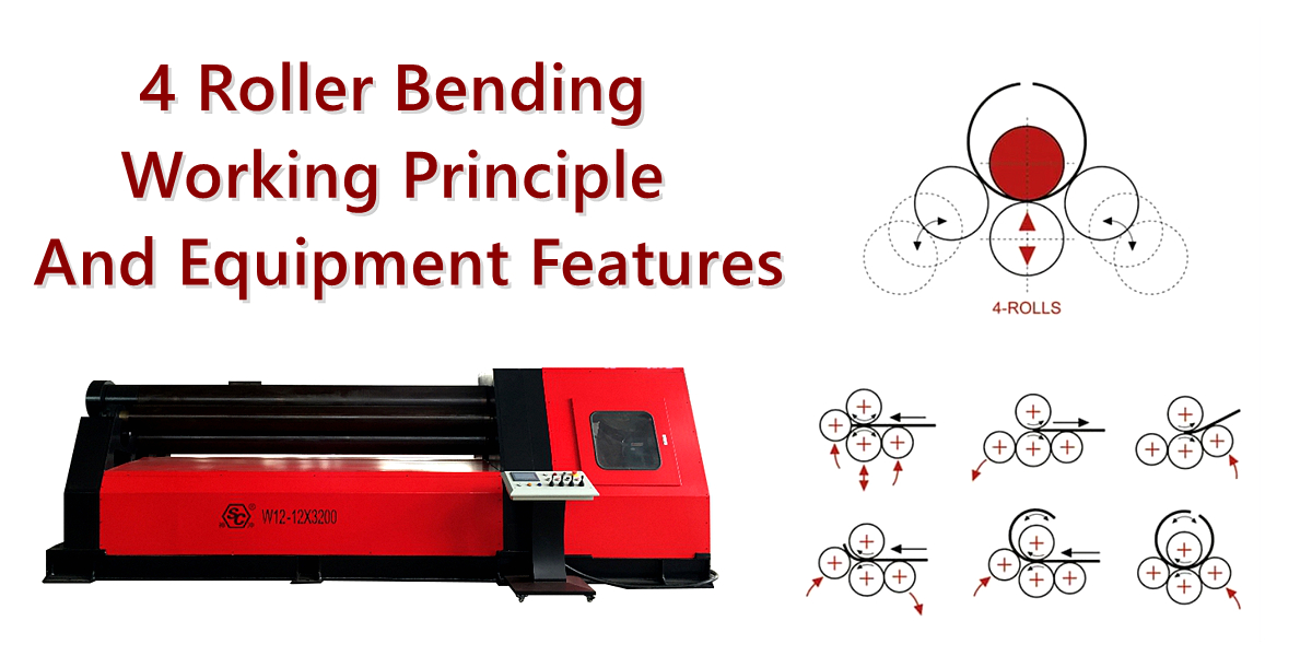
As a metal plate enters the space between the top and bottom rolls, the bottom roll exerts a clamping force. The main drive system propels the plate forward, while the side rolls apply a bending force, inducing a bending moment within the material.
Once the bending stress exceeds the material’s yield strength, the plate undergoes plastic deformation, retaining a specific curvature even after the load is removed.
The basic process can be summarized as follows:
Clamping and feeding
↓
Applying pressure via side rolls
↓
Plastic bending
↓
Cylindrical forming
2. Structure and Operating Principles of Four-Roll Bending Machines
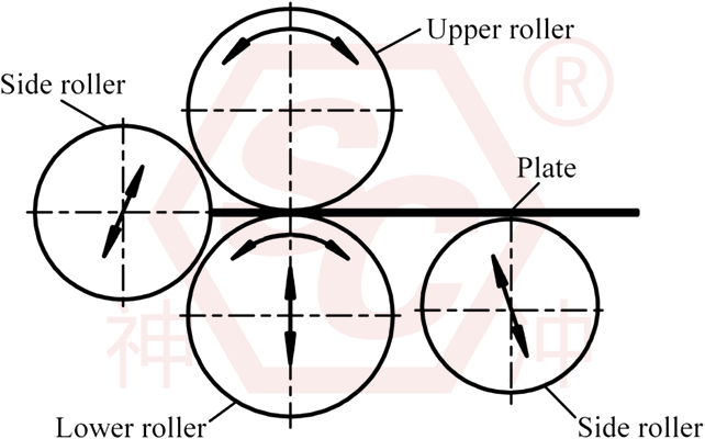
1) Clamping Action of the Top and Bottom Rolls
Upon entering the machine, the bottom roll moves upward, clamping the metal plate firmly between itself and the top roll.
This process serves three primary purposes: preventing the plate from slipping during the rolling operation, ensuring a continuous and stable feed, and enhancing positional control throughout the forming process.
2) Bending Deformation via Side Rolls
The left and right side rolls apply force through hydraulic cylinders, altering the stress state of the metal plate.
When the bending stress exerted on the plate exceeds the material’s yield strength, the plate undergoes plastic deformation—a change that is not fully reversible.
As the positions of the side rolls are adjusted, the bending radius of the plate changes accordingly.
Generally, assuming other conditions remain constant and the equipment’s operational limits have not been reached:
- Adjusting the side rolls upward increases the degree of bending, resulting in a smaller rolling radius.
- Adjusting the side rolls downward decreases the degree of bending, resulting in a larger rolling radius.
3) Continuous Rolling via Work Roll Rotation
The top roll (and any associated drive rolls) propels the plate forward through friction, while the side rolls continuously apply bending force, causing the plate to gradually develop a consistent curvature along its length. After one or more rounds of rolling, the plate is ultimately formed into the desired cylinder or circular arc.
3. Complete Processing Workflow for Four-Roll Plate Bending
The four-roll plate bending process generally consists of the following stages: material preparation, feeding and positioning, clamping, leading-edge pre-bending, trailing-edge pre-bending, continuous rolling, roundness calibration, and unloading.
Typical Process Flow:
1) Material Preparation
Verify the plate thickness, width, material grade, surface condition, and the quality of the cut edges. Confirm the target diameter and the required developed (unrolled) length.
2) Feeding and Clamping
Insert the plate between the top and bottom rolls, align its position, and apply the appropriate clamping force.
3) Leading-Edge Pre-bending
Adjust the position of the corresponding side roll while rotating the main rolls to bend the leading edge of the plate to the target curvature, thereby minimizing the residual straight edge.
4) Trailing-Edge Pre-bending
Reverse the feed direction and use the opposite side roll to pre-bend the trailing edge of the plate.
5) Continuous Rolling
Set the side rolls to the required positions and drive the plate through the bending zone to gradually form a complete cylinder.
6) Roundness Calibration
Measure the roundness, diameter, and the position of the seam; make incremental adjustments—accounting for material springback—to avoid over-bending.
7) Unloading and Inspection
Release the load, open the drop-end bearing (or end support) as specified by the equipment manufacturer, remove the workpiece, and inspect its dimensions and surface quality.
The specific pre-bending sequence and the movement patterns of the roll system may vary depending on the equipment; always follow the manufacturer’s operating procedures. When rolling large, thick plates, it may be necessary to adjust the side roll positions in multiple steps to avoid applying excessive force at once.
4. Ten Key Features of Four-Roll Plate Bending Machines
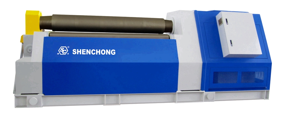
1) Superior Double-End Pre-bending Capability
Independent adjustment of the left and right side rolls allows for the pre-bending of both ends of the plate in a single setup. This effectively minimizes residual straight edges and improves the forming quality at the cylinder seam.
2) High Rolling Precision and Stability
The combination of top/bottom roll clamping and independently adjustable side rolls facilitates precise control over the rolling radius, prevents the plate from drifting, and ensures consistent quality in batch production.
3) Strong automated control capabilities
CNC-controlled models utilize position feedback, hydraulic control, and program management to automate roll positioning, process parameter storage, and the entire rolling sequence.
4) High production efficiency
By minimizing the need for flipping, repositioning, and secondary pre-bending, these machines are particularly well-suited for the batch production of cylindrical components.
5) Broad material compatibility
Depending on the equipment’s specifications, it can process carbon steel, stainless steel, aluminum alloys, and certain high-strength steel plates.
6) Versatile forming capabilities
Beyond simple cylinders, the equipment can produce arcs, ellipses, conical shapes, and components with varying curvatures.
7) Robust hydraulic drive
Hydraulic side rolls exert significant bending force, making the equipment suitable for processing medium-to-thick plates.
8) Reduced material waste
Pre-bending minimizes the length of straight edges, thereby reducing the need for subsequent trimming.
8) Easily integrated into automated systems
The equipment can be combined with feeding platforms, workpiece support frames, automatic centering devices, and CNC systems to form an automated rolling cell.
9) Improved welding quality
The consistent curvature at both ends of the rolled cylinder facilitates precise fit-up, tack welding, and subsequent final welding.
These characteristics generally align with the specifications provided by manufacturers for four-roll configurations and their associated forming processes; however, actual precision, production capacity, and automation capabilities will vary based on the specific equipment configuration.
5. Key Technical Parameters for the Four-Roll Rolling Process
Table of Key Technical Parameters:
Technical Specifications | Functions and Impacts |
Maximum Plate Rolling Thickness | Determines the maximum plate thickness that the equipment can process |
Maximum Pre-bending Thickness | Determines the capacity for pre-bending at both ends (typically less than the maximum plate-rolling thickness) |
Maximum Plate Rolling Width | Determines the axial length of the workpiece |
Minimum Rolling Diameter | Determines the minimum cylinder diameter that the equipment can form |
Upper Roll Diameter | Influences rolling capacity, rigidity, and the minimum forming radius |
Working Roll Rotation Speed | Affects production cycle time and process control |
Side Roll Adjustment Precision | Affects curvature control and repeatability |
Main Motor Power | Affects drive capacity and energy consumption |
Hydraulic System Pressure | Affects hydraulic cylinder thrust and load-bearing capacity |
CNC System | Determines capabilities related to automation, parameter storage, and program control |
Important Note:
The maximum plate thickness does not imply that the equipment can achieve this thickness for any plate width, material strength, or diameter. Actual capacity must be verified against the equipment’s rolling capacity curve.
6. Forming Calculations for Four-Roll Bending
1) Developed Length of the Plate
For an ideal cylinder, the length can be estimated based on the neutral axis:
L ≈ π(Di + Kt)
Where:
L: Developed length of the plate (mm)
Di: Target internal diameter of the cylinder (mm)
t: Plate thickness (mm)
K: Neutral axis position coefficient (approximately 0.5 for initial estimation; this should be adjusted based on the specific material and process).
For example, with a target internal diameter of 1000 mm, a plate thickness of 10 mm, and K = 0.5:
L ≈ 3.1416 * (1000 + 5)
L ≈ 3157.3 mm
This is a theoretical estimate. When preparing the material, factors such as weld gap, trimming allowance, springback, and results from trial rolling must also be considered.
2) Bending Strain of the Plate
During the 4 roller bending process, the outer layer of the plate is subjected to tension, while the inner layer is subjected to compression.
Under simplified pure bending conditions:
ε ≈ t / 2Rm
Where Rm is the bending radius near the neutral axis of the plate.
As the plate thickness increases or the target radius decreases, the bending strain generally increases, making the rolling process more difficult.
3) Springback Compensation
After the plate leaves the working rolls, it will undergo elastic springback; consequently, the actual diameter of the cylinder may be larger than the forming diameter applied during the rolling process.
Key factors influencing springback include the material’s yield strength, elastic modulus, plate thickness, target radius, and the rolling path.
In actual production, the compensation amount should be determined through measurements taken during trial rolling, rather than by applying a fixed compensation percentage.
7. Comparison of Four-Roll and Three-Roll Plate Bending Machines
Comparison Table:
Comparison Criteria | Four-roll plate bending machine | Three-roll plate bending machine |
Number of Work Rolls | 4 rolls | 3 rolls |
Plate Clamping | Independent clamping by the top and bottom rolls | Depends on the specific roll configuration |
Pre-bending of Both Ends | Process completed with a single setup | Some models require plate flipping or repositioning |
Residual Straight Edge | Typically shorter (cycle time) | Depends on the model and the pre-bending method |
Rolling Precision | Easier to achieve high repeatability | High-end models can also achieve high precision |
Automation Integration | Generally more convenient | Depends on the structure and control system |
Operational Complexity | Clamping and pre-bending are relatively straightforward | Varies according to the equipment design |
Equipment Investment | Typically higher (productivity/efficiency) | Some models have a lower cost |
Applicable Scenarios | Suitable for batch, high-efficiency, and automated production | General-purpose processing and a wide range of plate bending applications |
It should be noted that three-roll plate rolling machines come in various configurations—such as symmetrical, asymmetrical, and universal (top-roll adjustable) types—so it would be inaccurate to assume that no three-roll machine is capable of performing pre-bending on both ends of a plate.
Selection Conclusion:
For enterprises engaged in the mass production of cylindrical components that require high-precision pre-bending and frequent product changeovers, a four-roll plate rolling machine generally offers greater advantages. Conversely, for companies with limited budgets or those producing simpler, less varied components, a suitable three-roll machine can be a highly cost-effective choice.
8. Key Industries for Four-Roll Plate Rolling Applications
- Pressure Vessel and Storage Tank Manufacturing: Liquid storage tanks, chemical vessels, and pressure vessel shell segments.
- Wind Power and Energy Equipment: Wind turbine towers and large-scale cylindrical structural components for energy equipment.
- Shipbuilding and Offshore Engineering: Curved hull plates, marine cylindrical components, and structural parts.
- Steel Pipe and Metal Structures: Large-diameter welded steel pipes, flue ducts, and ventilation ducts.
9. Six Key Factors Affecting the Quality of Four-Roll Plate Rolling
1) Material Type and Yield Strength
Different materials require significantly different rolling forces. Even with the same thickness, materials with higher yield strength generally require a greater bending moment.
Therefore, the processing capability of a plate rolling machine cannot be determined solely based on the thickness of the plate.
2) Plate Thickness and Width
Greater plate thickness typically requires a larger bending moment; increased plate width can lead to greater roll deflection and higher total forming loads.
For a given material and curvature—based on a simplified elastic-plastic bending model—the bending moment required per unit of width is roughly proportional to the square of the thickness. However, the actual rolling load also depends on factors such as the distance between the rolls and specific operating conditions.
3) Rolling Diameter
A smaller target diameter generally requires a greater degree of plastic deformation in the plate.
The minimum rolling diameter achievable by a machine is constrained by factors including the diameter of the top roll, the arrangement of the rolls, material strength, plate thickness, and the overall rigidity of the equipment.
4) Material Elastic Springback
Once the rolling process is complete, the elastic strain within the material is released, typically causing the workpiece to exhibit an increase in diameter and a decrease in curvature. Therefore, in actual production, it is often necessary to intentionally over-bend the material, then achieve the target dimensions through subsequent measurement and roundness correction.
5) Roll Deflection and Parallelism
When processing wide plates, the rolls may deflect under load, which can lead to non-uniform curvature across the width of the workpiece.
Control measures must account for the rigidity of the equipment’s rolls, compensation design, and the actual width of the plate.
6) Feeding, Positioning, and Operational Procedures
Misalignment during feeding, insufficient clamping force, or inconsistent adjustment of the side rolls can result in issues such as taper, ovality, or seam misalignment.
Consequently, CNC parameters must be carefully coordinated with actual operational procedures.
10. How can the processing precision of four-roll bending be improved?
In practical production, optimization can be approached from three perspectives: equipment, process, and inspection.
Common Issues | Possible Causes | Improvement Measures |
Excessive ovality of the cylinder | Improper side-roller positioning, uneven springback | Implement multi-stage rolling, circularity correction, and parameter adjustment |
Presence of straight edges at the seams | Insufficient pre-bending | Optimize the end pre-bending process |
Tapering of the workpiece | Misaligned material feed, inconsistent roller-axis positioning | Verify plate centering and side-roll synchronization |
Bulging or “waisted” (hourglass) shape in the middle of the cylinder | Roller-axis deflection, material non-uniformity | Check equipment rigidity and roll-shaft compensation |
Surface indentations | Contamination on roller surfaces, excessive clamping force | Clean roll surfaces and optimize clamping pressure |
Dimensional fluctuations during repeated processing | Variations between material batches, unstable process parameters | Categorize process programs and perform first-article inspection |
For plates with high surface quality requirements—such as those made of stainless steel—additional measures can be implemented, including the use of protective roller coverings, specialized contact materials, and anti-scratch precautions.
11. How do you select the right four-roller plate rolling machine?
When selecting a machine, it is recommended to first determine five fundamental process parameters: material type and yield strength, maximum plate thickness, maximum plate width, minimum internal rolling diameter, and whether pre-bending of both plate ends is required.
Taking the common W12 series hydraulic four-roller plate rolling machine as an example, the following parameters should be prioritized during the selection process.
Technical Specifications | Description |
Maximum Plate Rolling Thickness | Maximum rolling thickness for specified material, width, and diameter conditions |
Maximum Pre-bending Thickness | Maximum plate thickness for which the equipment can perform edge pre-bending |
Maximum Plate Rolling Width | Maximum allowable plate width for processing |
Minimum Rolling Diameter | Minimum workpiece diameter achievable under specified operating conditions |
Upper Roll Diameter | Affects rigidity and the capability to roll small-diameter workpieces |
Lower Roll Diameter | Affects clamping and feeding performance |
Side Roll Diameter | Affects the load-bearing capacity of the side rolls and the overall rolling range |
Rolling Speed | Linear speed of the plate during the rolling process |
Main Motor Power | Related to drive capacity and equipment specifications |
Hydraulic System Pressure | Rated operating pressure of the hydraulic system |
CNC System | Controls roll positioning, operational sequences, and processing programs |
Total Machine Weight | Related to the equipment’s structure, specifications, and load-bearing capacity |
Taking common four-roll plate rolling machines—such as the W12-16×2000 and W12-25×3200 models—as examples, the numbers in the model designation typically indicate the nominal plate-rolling thickness and working width. However, actual capacity should always be verified against the manufacturer’s technical specifications and test-rolling results.
For a W12-25×3200 four-roll plate rolling machine, the model designation implies a nominal rolling capacity of 25 mm in thickness and 3200 mm in width. It is important to note that this thickness capacity is contingent upon specific parameters defined by the manufacturer—such as material strength, minimum rolling diameter, and pre-bending conditions—and should not be interpreted as an absolute capability to roll 25 mm thick plates under any and all operating conditions.
For facilities primarily engaged in the batch production of cylindrical components, priority should be given to features such as CNC control, automatic centering, roll-position feedback, hydraulic synchronization, automated feeding, and auxiliary support systems. Conversely, for operations involving small-batch, high-variety production, greater emphasis should be placed on ease of operation, efficiency in tooling or process changeovers, and the overall capital investment cost.
12. Conclusion: The Core Value of Four-Roll Rolling Process
The advantage of the 4 roller bending lies not merely in the addition of an extra working roll; more importantly, it enables pre-bending, rolling, and calibration (rounding) to be performed on a single machine. This is achieved through the stable clamping provided by the top and bottom rolls, combined with the independent forming action of the side rolls.
From a production standpoint, a four-roll plate rolling machine minimizes the need for plate handling and repeated positioning, enhances the consistency of cylindrical forming, and serves as an ideal foundation for automated rolling production lines.
For manufacturers in sectors such as pressure vessels, storage tanks, steel structures, shipbuilding, and energy equipment, the four-roll plate rolling machine is particularly well-suited for applications that demand high production efficiency, superior rolling quality, and consistent repeatability across batch runs.
 English
 Spanish
 Portuguese
 Russian
 Arabic
 French
 Italian
 German
 Polish
 Thai
 Vietnamese
 Lithuanian
 Czech
 Korean
 Japanese
 Chinese