
Table of Contents
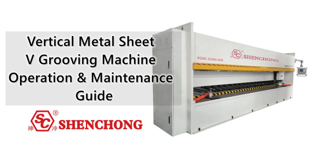
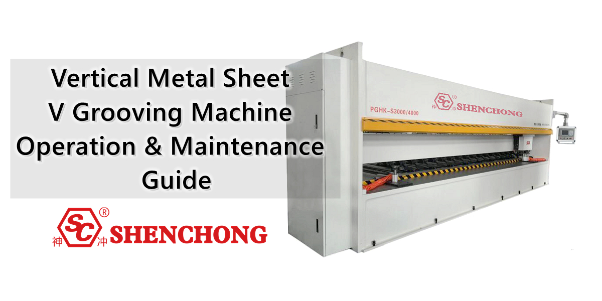
The vertical metal sheet v grooving machine is a CNC machine specifically designed for processing V-grooves in metal sheets. It is widely used in stainless steel decoration, building curtain walls, elevator manufacturing, metal furniture, kitchen and bathroom equipment, precision sheet metal, and high-end metal products industries.
Compared to traditional direct bending processes, the vertical grooving machine reduces local residual thickness by processing V-grooves at predetermined bending positions on the sheet metal, making it easier to form small rounded corners, clear edges, and a refined bent appearance.
This article systematically introduces the correct operation and use of the vertical metal sheet grooving machine, covering aspects such as equipment structure, working principle, operation procedures, CNC parameter settings, tool selection, processing techniques, safety regulations, daily maintenance, common faults, and solutions.
1. Structure And Working Principle of Vertical Metal Sheet V Grooving Machine
1) Main Structure of the Equipment
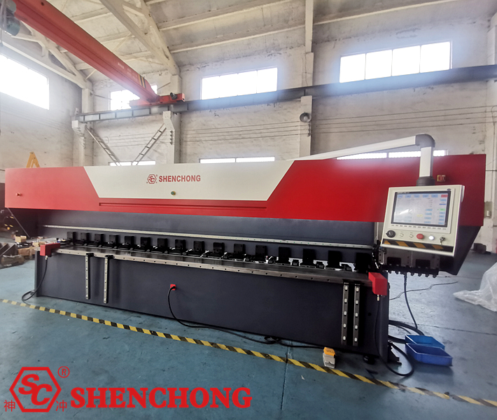
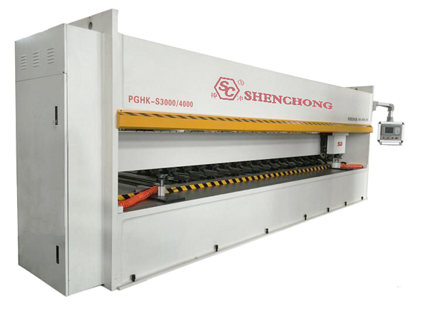
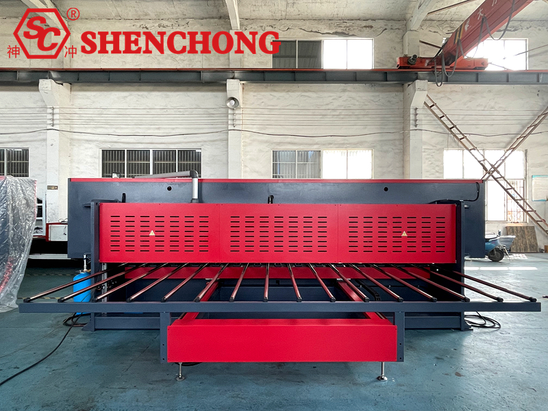
A typical vertical CNC grooving machine mainly consists of a frame, worktable, tool holder, CNC system, positioning system, hydraulic or pneumatic clamping device, lubrication system, and safety protection system.
Components Table:
Main Components | Functions |
High-rigidity frame | Supporting equipment, reducing processing vibration and structural deformation |
Worktable | Bearing and positioning metal sheets |
CNC system | Controlling groove position, processing depth, feed rate, and processing program |
Tool post and cutting tools | Completing V-groove cutting of metal sheets |
Servo drive system | Controlling tool holder movement and positioning axis |
Clamping device | Preventing sheet metal movement or vibration during processing |
Positioning and stopping device | Ensuring accurate grooving position |
Lubrication system | Reducing friction and wear of moving parts |
Electrical control cabinet | Implementing power supply, control, protection, and fault diagnosis |
Safety protection devices | Reducing the risk of personnel contact with moving parts and flying debris |
Vertical grooving machines from different manufacturers may vary in tool holder direction, clamping method, number of axes, and control system. The actual configuration of the equipment should be considered.
2) Working Principle
The vertical metal sheet V grooving machine uses a CNC system to control the tool to cut along a preset trajectory, forming a V-shaped groove of specified depth and angle on the sheet surface.
The basic processing flow is as follows:
Sheet placement and positioning
↓
Pressing and fixing the sheet
↓
CNC system executes the grooving program
↓
Tool cuts in layers to the set depth
↓
Check groove position, groove shape, and remaining thickness
↓
Complete processing and proceed to the subsequent bending process
3) Grooving Depth and Remaining Thickness
The core of grooving processing lies in controlling the groove depth and the remaining thickness at the bottom of the groove.
d = t – r
Where:
d: Groove depth, mm
t: Actual sheet thickness, mm
r: Remaining thickness at the bottom of the groove, mm
For example, if the sheet thickness is 2.0 mm and the designed remaining thickness is 0.6 mm, then:
d = 2.0 – 0.6 = 1.4 mm
Special note:
The remaining thickness is not necessarily better the thinner it is. Too thin a thickness may lead to cracking at the bending point, insufficient strength, and processing deformation. The final value should be determined based on the material, bending angle, stress requirements, and sample verification.
2. Pre-Start Preparation and Equipment Inspection
Proper pre-start inspection is crucial for ensuring machining accuracy, production efficiency, and equipment safety.
1) Vertical Metal Sheet V Grooving Machine Inspection Checklist
8 Pre-Start Inspection Items:
Confirm power supply voltage, grounding, and electrical connections are normal.
- Check emergency stop button, safety guards, and interlocking devices.
- Check guide rails, lead screws, and lubrication system status.
- Check cutting tools for chipping, cracks, or looseness.
- Check the cleanliness of the worktable and positioning stops.
- Check the status of hydraulic or pneumatic clamping devices.
- Verify the material, thickness, and machining drawings of the sheet metal.
- Confirm the machining area is unoccupied and free of obstructions.
If any abnormalities are found during the inspection, stop the machine and have it handled by qualified personnel. Do not continue operation by short-circuiting interlocks or disabling alarms.
2) Sheet Metal Preparation
Before machining, ensure the sheet metal surface is free of obvious oil stains, foreign objects, severe warping, and non-compliant deformation.
Special attention should be paid to:
- Stainless steel mirror panel: Prevent surface scratches during positioning, clamping, and cutting processes.
- Aluminum Plate: Note that the material is relatively soft; avoid excessive compression that could cause surface indentations.
- Carbon Steel Plate: Pay attention to surface oxide scale, material hardness, and cutting load.
- Longer or Thinner Plates: Ensure sufficient support throughout the process to prevent deformation due to suspension.
3. Standard Operating Procedure for Vertical Metal Sheet Grooving Machine
Step 1: Start the Equipment
Start the main power supply, control system, and related auxiliary systems according to the equipment manufacturer’s specified startup sequence.
After the system completes its self-check and confirms there are no outstanding fault alarms, then perform the required zeroing or reference point operation.
Note: Before zeroing, ensure the tool holder and motion mechanism are in a safe state to avoid collisions with the sheet metal or fixtures.
Step 2: Input the Machining Program
Set the sheet metal dimensions, grooving position, groove depth, tool parameters, feed rate, and number of passes according to the drawing requirements.
Some CNC systems support graphical programming, groove list, multi-grooving batch processing, and program storage functions.
Step 3: Install and Position the Sheet Metal
Place the sheet metal on the worktable and position it using the positioning stop and reference edge.
Operators should ensure the sheet metal is flat and adheres well to the support surface, and check that the grooving direction meets process requirements.
Step 4: Clamping the Sheet Metal
Initiate the clamping action as specified by the equipment to confirm that the sheet metal is reliably fixed.
Insufficient clamping force will cause sheet metal vibration and groove misalignment; excessive clamping force may lead to sheet deformation or surface damage.
Step 5: Trial Run
When processing a new program for the first time, perform program checks, no-load runs, or safety simulations according to the manufacturer’s specifications, and conduct trial cuts with conservative parameters.
Trial cuts should focus on checking the groove position, tool movement direction, clamping status, tool interference risk, and actual remaining thickness.
Step 6: Formal Processing
After successful trial cut, start the automatic processing program.
During processing, monitor equipment operating noise, vibration, chip removal, and CNC system alarms.
Do not reach in to clean chips, adjust the sheet metal, or touch the processing area while the tool is moving.
Step 7: Inspecting the Finished Product
After processing is completed and the tool is confirmed to be stopped and the equipment is in a state where it can handle material, remove the sheet metal and perform a quality inspection.
Key measurements include the groove location, groove depth, remaining thickness at the bottom of the groove, and groove shape consistency.
Step 8: Shutdown and Cleaning
After processing, stop the equipment in the designated safe position and shut down the auxiliary systems, CNC system, and main power supply according to the operating procedures.
Use appropriate tools when cleaning the worktable and chips; never handle sharp metal chips directly with your hands. When maintenance, tool disassembly, or entering hazardous areas, implement power disconnection and accidental start-up prevention measures.
4. CNC V Grooving Machine Machining Parameter Settings
Grooving parameters directly affect machining accuracy, tool life, slot surface quality, and subsequent bending effects.
1) Main Parameters and Their Functions
Parameters | Main impacts | Setting Principles |
Sheet thickness | Determines the basis for calculating groove depth | Input based on actual measured thickness |
Groogging position | Determines subsequent bending dimensions | Determine based on unfolded diagram and reference edge |
Groogging depth | Affects bending resistance and residual strength | Combined with bending requirements and sample verification |
Tool angle | Affects groove shape and bending geometry | Select based on target bending angle and springback |
Cutting speed | Affects processing efficiency, temperature rise, and wear | Determine based on material and cutting tool |
Single cutting depth | Affects cutting load and groove surface quality | Avoid exceeding the allowable range of equipment and cutting tool. Deep grooves are usually machined in layers |
Number of cuts | Affects final depth and efficiency | Ensure reliable fixation and no surface damage |
Clamping state | Affects sheet metal stability | Input based on actual measured thickness |
2) Processing characteristics of different materials
Materials | Groov Characteristics | Key Precautions |
304 Stainless Steel | High toughness, prone to work hardening | Keep tools sharp and avoid repeated rubbing |
316 Stainless Steel | Significant cutting resistance and work hardening issues | Properly control depth of cut and tool wear |
201 Stainless Steel | Performance is affected by specific grades and conditions | Confirm parameters with a trial cut |
Aluminum Alloy | Some grades are prone to tool sticking | Use tools and chip removal methods suitable for aluminum |
Q235 Carbon Steel | Oxide scale and material condition must be considered | Pay attention to cutting load and tool wear |
Copper Plate | Significant material ductility and adhesion properties | Control burrs, built-up edge, and surface quality |
Recommended cutting speeds, depths of cut, and tool types for different materials cannot be determined solely by material name; material hardness, tool grade, equipment rigidity, and tool holder structure must also be considered.
5. Grooving Techniques for Different Materials
1) Stainless Steel Plates
Stainless steels such as SUS304 and SUS316 exhibit a significant tendency for work hardening. Sharp blades suitable for stainless steel should be selected, repeated friction and excessive depths of cut should be avoided, and tool wear checks should be prioritized.
2) Aluminum Alloy Plates
Aluminum is prone to tool sticking and built-up edge. Appropriate tool geometry should be selected, the cutting edge kept sharp, and lubrication and chip removal methods optimized according to equipment limitations.
3) Carbon Steel Plates
Cutting parameters should be selected based on the steel grade, strength, and actual plate thickness. Grooving thick plates requires special attention to tool holder rigidity, cutting resistance, and the remaining thickness at the bottom of the groove.
4) Copper and Brass Plates
The feed rate and cutting speed should be controlled according to the hardness of the copper material to avoid material compression, increased burrs, and uneven groove bottom surface.
6. Selection and Use of Grooving Tools
Tools are a crucial factor determining the quality of V-groove machining.
1) Common Tools
Vertical grooving machines typically use carbide tools or indexable inserts. The specific tool structure depends on the machine model.
Tool selection should consider:
Tool material and coating.
Tool tip angle and cutting edge shape.
Hardness and toughness of the workpiece material.
Target groove width, groove depth, and groove surface quality.
Tool clamping stability and the machine’s allowable cutting load.
2) Tool Angle Selection
Common V-groove tools can use different included angles, such as 60°, 90°, or other specialized angles, but the tool included angle is not necessarily equal to the final bending angle.
For example, for a workpiece with a target 90° bend, the groove shape, bending direction, material springback, and remaining thickness must be comprehensively considered. It cannot be simply assumed that using a 90° tool will necessarily result in a 90° bend angle.
3) Precautions for Tool Replacement
Before replacing the tool, the equipment must be placed in the safe maintenance condition specified by the manufacturer, and necessary energy isolation must be performed.
During installation, clean the tool holder contact surface, check for tool damage, and secure the tool using the specified fasteners and torque. After replacement, perform tool parameter calibration and test cutting according to equipment requirements.
7. How to Improve the Machining Accuracy of Vertical Grooving Machine?
The main factors affecting slotting accuracy include equipment rigidity, positioning system, sheet metal condition, tool wear, clamping reliability, and CNC parameters.
1) Improving Positioning Accuracy
Clean the positioning reference surface before machining and check for looseness or significant gaps in the stop mechanism. For multi-slot workpieces, use a consistent positioning reference as much as possible to reduce repeated clamping errors.
2) Controlling the Remaining Thickness at the Slot Bottom
The stability of the remaining thickness at the slot bottom directly affects the consistency of subsequent bending.
It is recommended to control this by measuring the actual sheet thickness, verifying the tool zero position, monitoring tool wear, and checking the flatness of the worktable.
3) Reduce machining vibration
Equipment vibration can cause tool marks, dimensional deviations, and tool chipping on the groove surface.
The tool clamping and clamping condition, feed parameters, and mechanical transmission system should be checked. If necessary, the single-cut load should be reduced.
4) Control burrs and surface quality
Keep the tool sharp, select appropriate cutting parameters, and avoid generating severe built-up edge during machining. For decorative panels with high surface finish requirements, the groove surface roughness and surface protection scheme should be verified through trial cuts.
8. Coordination of Vertical Grooving Machines with Subsequent Bending Processes
The ultimate goal of vertical metal sheet v grooving machines is usually not simply to create V-grooves, but to create conditions for subsequent high-quality bending.
By properly controlling the groove depth and shape, the following process effects can be achieved:
- Reducing the local material thickness at the bending point, thereby reducing the required bending force.
- Achieving smaller outer radius corners at bends, improving the appearance of decorative parts.
- Improving the controllability of bending forming for complex sheet metal products.
- Improving the consistency of repeated processing after proper process verification.
- Reducing the dimensional design limitations of some decorative panels caused by large radius corners.
It should be noted that grooving cannot completely eliminate material springback, nor can it guarantee that the bending point will not crack. For load-bearing components, components subjected to repeated stress, or products with fatigue requirements, strength checks and necessary testing verification must be performed.
9. Common Faults & Solutions
Fault Symptoms | Possible Causes | Troubleshooting and Handling Directions |
Inconsistent groove depth | Sheet thickness fluctuation, tool wear, positioning or table abnormality | Measure plate thickness, inspect cutting tools and reference points |
Groove position deviation | Positioning error, sheet material movement, transmission clearance | Inspect the material stop and clamping system |
Rough groove surface | Tool wear, parameter mismatch, vibration | Inspect the cutting tools and cutting parameters |
Excessive burrs | Cutting edge dulling, material sticking to the tool | Replace or adjust the cutting tools |
Tool chipping | Excessive cutting load, impact, abnormal clamping | Inspect the depth of cut, clamping, and material |
Sheet material vibration | Insufficient clamping, inadequate support | Inspect the clamping and plate support |
Abnormal tool holder operation | Guide rail, transmission, servo system malfunction | Inspect by qualified personnel after machine shutdown |
System alarm | Sensor, drive, electrical, or program abnormality | Troubleshooting based on alarm codes |
In case of dangerous situations such as tool collision, severe abnormal noise, tool breakage, or clamping failure, the equipment’s prescribed safety shutdown measures should be taken immediately. Production can only be resumed after the cause has been identified.
10. Daily Maintenance and Care
- Every shift: Clean chips, inspect tools, worktable, clamping device, and alarm records.
- Weekly: Check lubrication status, positioning mechanism, and visible fasteners.
- Monthly: Inspect guide rails, transmission mechanism, hydraulic or pneumatic system, and safety devices.
- Quarterly: Check positioning accuracy, repeatability, and mechanical condition according to the equipment manual.
- Annually: Conduct comprehensive accuracy checks, electrical safety checks, and preventative maintenance.
The above is a general maintenance plan. Lubricant type, lubrication cycle, hydraulic pressure, tightening torque, and calibration methods should strictly follow the manufacturer’s instructions for the specific machine model.
11. Ten Key Precautions for Operating CNC Vertical V-Grooving Machine
- Operators must be trained on the equipment and familiar with the CNC system and safe operating procedures.
- Before processing, the material, thickness, and processing dimensions of the sheet metal must be confirmed.
- Tools must be securely installed; blades with cracks or obvious chipping must not be used.
- Adjusting the sheet metal or cleaning chips while the cutting tool is in motion is strictly prohibited.
- The sheet metal thickness, processing range, and cutting capacity of the equipment must not be exceeded.
- A trial cut and dimensional inspection must be performed on the first piece processed.
- Safety interlocks or equipment alarms must not be arbitrarily disabled.
- Appropriate anti-scratch measures should be taken for materials with high surface finish requirements, such as mirror stainless steel.
- If abnormal vibration, unusual noise, or sudden changes in cutting load are detected, the machine should be stopped immediately for inspection.
- Prescribed energy isolation measures must be implemented before changing tools, performing maintenance, and entering hazardous areas.
12. Summary: How to correctly use a vertical metal sheet grooving machine?
A vertical metal sheet v grooving machine is a specialized device for precision V-grooving of the surfaces of metal sheets such as stainless steel, carbon steel, aluminum, and copper. It is widely used in industries such as stainless steel decoration, metal curtain walls, elevator manufacturing, kitchen equipment, sheet metal processing, chassis and cabinets, and high-precision bending forming.
Unlike direct bending of ordinary sheet metal, vertical sheet metal grooving machines can process V-grooves of a certain depth and angle at predetermined bending positions. This reduces local bending resistance, making subsequent bending easier to achieve smaller outer radii and clearer bend lines.
The key to operating a CNC vertical sheet metal grooving machine is not just completing the V-groove cutting, but establishing a complete processing flow from material inspection, process calculation, equipment positioning, tool selection, trial cutting inspection to subsequent bending.
For actual production, it is recommended to establish three key standards: a first-piece inspection system, a grooving process database for different materials, and a daily equipment inspection and maintenance system. This will ensure safety while improving groove depth consistency, reducing tool wear, and stabilizing the quality of subsequently bent products.

 English
 Spanish
 Portuguese
 Russian
 Arabic
 French
 Italian
 German
 Polish
 Thai
 Vietnamese
 Lithuanian
 Czech
 Korean
 Japanese
 Chinese