
Table of Contents
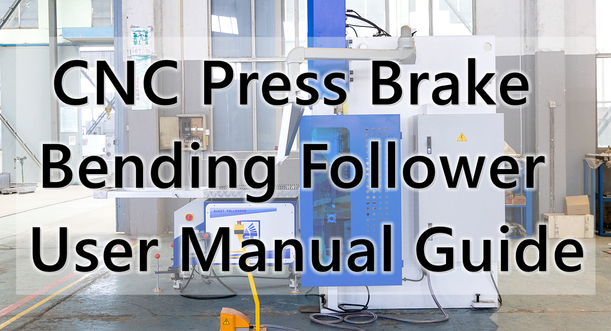
CNC press brake bending follower support device is an auxiliary device installed in front of the bending machine to support large or heavy sheet metal. It reduces sheet metal sagging, offset, surface scratches, and operator fatigue by synchronously adjusting the angle and movement trajectory of the support platform during the bending process.
This manual systematically explains the equipment structure, working principle, installation and commissioning, operating procedures, parameter settings, safety regulations, maintenance, and common faults. It can serve as a reference document for equipment delivery training, on-site operation, and daily maintenance.
Scope of Application for the Bending Follow-up User Manual:
CNC hydraulic press brakes, hybrid servo press brakes, large sheet metal bending equipment, and supporting follow-up material support systems.
Important Note:
Follow-up material support devices from different manufacturers, models, and control systems vary in the number of servo axes, load capacity, installation method, synchronous control, and safety logic.
This document is a general operation manual. Actual use must be based on the equipment nameplate, manufacturer’s instructions, electrical drawings, and on-site acceptance parameters.
1. Overview of CNC Press Brake Bending Follower Equipment
1) What is a Bending Followe Support Device?
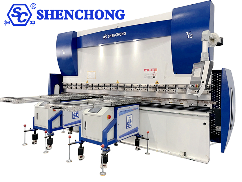
A bending follow-up device is a sheet metal support system used in conjunction with a bending machine. During bending, one side of the sheet metal is clamped by the upper and lower dies of the bending machine, while the other side may sag or rotate due to its own weight. The CNC press brake bending follower supports the sheet metal and follows its rotation, helping to maintain a stable motion posture.
- Initial Material Support State
The sheet metal is placed on the material support platform, and the material support device is in standby or initial position. The operator completes positioning, straightedge adjustment, and workpiece confirmation.
- Follow-up Bending State
As the slider descends and the sheet metal gradually bends, the material support platform adjusts its angle according to the set trajectory or control system instructions, continuously supporting the sheet metal.
- Return and Unloading State
After bending is completed, the material support device returns to a safe position or enters the next step position according to the program, facilitating material removal, flipping, or continuous bending.
2) Main Applications
- Sheet Metal Support
During sheet metal bending, the support arm follows the sheet metal’s movement, providing support and reducing the risk of sagging in long, wide, and large thin sheets.
- Improved Bending Stability
Reduces swaying, positional shifts, and localized deformation caused by the sheet metal’s own weight, helping to maintain consistency in bending dimensions and angles.
- Reduced Labor Intensity
For large air conditioning panels, elevator panels, cabinet housings, and long sheets, the support arm reduces the burden on operators who need to continuously lift the sheets.
- Supports Semi-Automatic Bending
Can work in conjunction with CNC bending machine control systems, participating in program control in suitable configurations to help achieve a more stable and repeatable bending process.
3) Application Industries
- Air Conditioning and Refrigeration Equipment: Large housings, ducts, heat exchanger outer panels.
- Elevator Manufacturing: Car panels, door panels, decorative panels.
- Electrical and Cabinet Systems: Distribution cabinets, control cabinets, server cabinets.
- Construction Machinery: Protective covers, structural components. Stainless steel processing: large decorative panels, equipment housings.
- Ventilation and environmental protection equipment: air ducts, dust removal equipment housings.
- New energy equipment: battery equipment housings, energy storage cabinet sheet metal parts.
2. Equipment Structure and Main Components
List of Main Components:
Components | Main Functions | Operation & Maintenance Focus |
Carrying frame | Support the entire mechanism and transfer loads | Inspect fixing bolts, welds, and structural deformation |
Material support platform | Support the free end of the sheet metal | Inspect surface wear, cleanliness, and levelness |
Follow-up support arm | Support and drive the platform rotation | Inspect clearances, connecting pins, and motion interference |
Servo motor and driver | Control position, speed, and motion trajectory | Inspect alarms, overloads, and electrical connections |
Transmission mechanism | Transmit driving force to the support platform | Inspect gears, lead screws, reducers, or connecting rods |
Position feedback element | Provide position or angle feedback | Inspect encoders, sensors, and feedback signals |
Control system | Coordinate the bending machine and material support actions | Inspect parameters, programs, and communication status |
Safety device | Provide emergency stop, limit switches, and necessary safety features | Perform functional tests as specified by the manufacturer |
Different devices may not include all of the above components. Some models use independent controllers, while others are directly linked to the bending machine’s CNC system; the drive method may also be servo electric or hydraulic drive.
3. Working Principle and Synchronization Control
1) Basic Working Principle
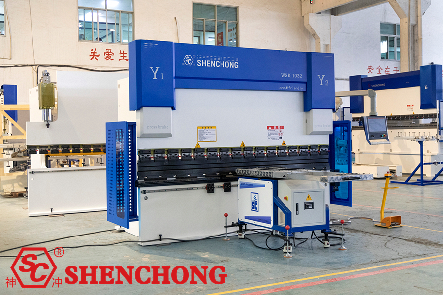
The core task of the CNC press brake bending follower system is to adjust the position or angle of the material support platform based on the movement of the bending machine’s slider and the rotation of the sheet metal, ensuring continuous and stable support for the sheet metal during bending.
Flow:
Bending machine slider position / motion signal
↓
Controller calculates the follow-up trajectory and target position
↓
Servo driver controls the motor and mechanical transmission mechanism
↓
Material support platform follows the sheet metal movement and provides support
↓
Position feedback and subsequent motion correction (e.g., configuring closed-loop feedback)
This is a typical control architecture diagram. The actual signal source, feedback method, and control sequence should be based on the specific equipment’s electrical drawings.
Taking a common servo follow-up device as an example, its working process includes:
- Signal acquisition: Obtaining slider position, motion status, or feedback from dedicated sensors.
- Trajectory Calculation: The controller calculates the target position based on the slider movement, set parameters, and follow-up curve.
- Drive Execution: The servo system drives the material support arm or platform to move.
- Synchronous Following: The platform adjusts according to the bending angle of the sheet metal.
- Return Reset: After bending, the system returns to the set position according to the program.
2) Main Movement Modes of the Follow-up Device
A. Rotary Follow-up
The material support platform rotates around a fulcrum, following the bending angle of the sheet metal. Commonly used in bending conditions requiring support of the free end of the sheet metal.
B. Lifting Adjustment
Used to adapt to different mold heights, workpiece heights, or equipment installation positions. Lifting may be manually adjusted or performed by a motor or other drive mechanism.
C. Auxiliary Movement
The material support surface uses ball bearings, rollers, or other low-friction structures to facilitate sheet metal positioning, movement, and flipping. Not all material support platforms are equipped with these structures.
3) Which parameters affect CNC press brake bending follower effect?
Influencing Factors | Potential problems | Adjust direction |
Follow-up starting position | Loss of support or interference when the sheet metal bends | Calibrate according to workpiece and mold positions |
Follow-up speed | Platform cannot keep up with the sheet metal or moves too fast | Adjust speed curve according to equipment manual |
Follow-up angle | Platform and sheet metal posture mismatch | Recalibrate angle or trajectory |
Sensor feedback | Following delay, position error | Check signal and sensor installation |
Workpiece weight and center of gravity | Unstable support, drive overload | Recalculate load and support position |
Mold opening and height | Inappropriate platform position or collision | Readjust mechanical position and process parameters |
Key Principle:
Do not simply set the follow-up speed to maximum. Appropriate speed, angle, starting position, and return trajectory are more important than simply increasing the speed.
4. Installation And Mechanical Adjustment
Installation and initial commissioning are recommended to be performed by the equipment manufacturer or qualified technicians. Installation location and clearance vary depending on the equipment structure. Dimensions from other models cannot be directly applied to this machine.
1) Pre-Installation Preparation
Before installation, confirm the following items:
- Verify the follow-up device model, rated load, and bending machine model.
- Inspect the frame, material support surface, support arm, and transmission components for damage.
- Confirm that the equipment installation foundation or movable base meets the requirements.
- Confirm that the power supply voltage, grounding, and electrical interfaces meet the equipment requirements.
- Prepare equipment drawings, wiring diagrams, and installation instructions.
- Clear the area in front of the bending machine, leaving space for the material support device to move.
- Based on the on-site risk assessment, implement power-off, tagging, and accidental start-up prevention measures.
2) Mechanical Installation Steps
– Positioning the CNC press brake bending follower
Move the follow-up device to the designated position in front of the bending machine, ensuring there is no interference between the material support platform, support arm, and the working area of the bending machine.
– Adjusting the Height
Adjust the material support height according to the working surface of the lower die of the bending machine, the die height, and the workpiece support requirements. Whether it should be flush, slightly lower, or use other settings must be followed according to the manufacturer’s specifications.
– Adjusting the Front-to-Back Distance
Ensure the material support surface is in a position that can effectively support the workpiece, while ensuring that the sheet metal will not impact the material support surface or mechanism during rotation.
– Checking the Left-to-Right Position
Confirm that the material support device matches the workpiece’s center of gravity, bending length, and support range. When using multiple material support devices, also check for interference between them.
– Secure and Recheck
Tighten the mechanical connections, caster brakes, or foot fixings as specified, and check the levelness and clearance.
3) Electrical Connections and Signal Checks
Electrical wiring should be completed by qualified electrical personnel according to the equipment drawings. Do not judge the wiring method solely by cable color or interface appearance.
The main inspection items include:
Inspection Items | Acceptance Requirements |
Main Power Supply | Voltage, frequency, and protection configuration meet nameplate requirements. |
Protective Grounding | Grounding connection is reliable. |
Servo Driver | Model matches, no abnormal alarms. |
Position Sensor | Installation is secure, signal changes are correct. |
Control Communication | Bending machine and servo device signals conform to interface definitions. |
Limit Switches and Emergency Stops | Inspection and functional testing are completed according to design logic. |
Cable Layout | No friction, compression, or entanglement with moving parts. |
Special Note:
If using an external magnetic scale, independent PLC, or dedicated slider displacement sensor, strictly follow the wiring diagram of the corresponding model during installation. Do not arbitrarily connect signals, modify the bending machine’s safety circuit, or bypass protection functions.
5. Start-up, Debugging And First Run
1) Pre-Start-up Checklist
Before starting each shift, the operator should complete the following checks:
Mechanical Structure:
- The material support platform, support arm, and frame have no obvious deformation or cracks.
- Connecting bolts, braking devices, and fixing mechanisms are reliable.
- The movement path is free of tools, scrap, or other obstacles.
Electrical System:
- Power supply, grounding, and control panel are in normal condition.
- Sensors and drivers have no abnormal alarms.
- Emergency stop and limit devices are in normal condition.
Workpiece and Mold:
- Workpiece dimensions, weight, and center of gravity meet the equipment’s capabilities.
- The mold is installed correctly, and the material support platform matches the workpiece’s movement path.
- The sheet metal has no abnormal conditions that could cause slippage or instability.
2) Initial Start-up Procedure
Equipment Start-up:
After confirming the work area is clear, start the bending machine and follow-up device sequentially according to the manufacturer’s instructions.
Control Interface Check:
Confirm the display is normal, communication status is correct, and there are no unprocessed driver or sensor alarms.
Zero Return:
Return the relevant axes to the reference position as required by the instruction manual. If the equipment requires the bending machine slide to return to zero first, strictly adhere to its starting sequence.
Manual Mode Selection:
Use jogging or manual operation to check the movement direction, limit switches, and return action of the follow-up device. Manual mode does not eliminate the risk of safety function failure.
No-Load Test:
With no workpiece, verify each movement direction and range of motion at the equipment’s specified safe speed.
Test Piece Bending:
Using a validated test piece and low-risk process conditions, check if the material support action matches the sheet metal movement.
Production After Confirmation:
Verify bending quality, material support stability, movement clearance, and safety device functionality, and record the debugging results.
3) How to Set Key Parameters?
Parameters | Setup Principles | Common Errors |
Original Position | Calibrate according to the equipment reference point program | Origin misalignment causing abnormal stroke |
Starting Position | Ensure workpiece placement and initial support stability | Insufficient material support before sheet metal bending |
Follow-up Speed | Match the bending speed and workpiece characteristics | Mismatch caused by excessively slow or fast speed |
Follow-up Angle | Set according to workpiece shape and control logic | Relative sliding between the material support surface and the sheet metal |
Return Position | Ensure sufficient space for unloading, flipping, and the next step | Impact on the workpiece or mold during return stroke |
Limit Position | Calibrate based on the actual allowable stroke of the mechanism | Motion exceeding limits or premature triggering of limit switches |
Load Setting | Do not exceed the nameplate and specified operating conditions | Overload, deformation, or actuator alarm |
The parameter names and setting logic of different controllers are not uniform. During initial debugging, the original values should be recorded item by item, and parameters should be backed up before modification. Safety-related parameters should not be modified arbitrarily, nor should alarms be disabled.
6. Standard Follow-up Bending Operation Procedure
The following procedure applies to common semi-automatic bending conditions with manual feeding and follow-up auxiliary support.
Step 1: Confirm Process and Workpiece
Check the material, thickness, length, weight, bending direction, mold opening, and process sequence of the sheet metal.
Confirm that the load-bearing capacity of the follow-up device is sufficient to meet the actual support conditions.
Step 2: Adjust Material Support Position
Adjust the material support height, front-to-back position, and left-to-right position according to the workpiece size. Confirm that the workpiece is placed stably and will not tilt due to its own weight or eccentric load.
Step 3: Select Operating Mode
Select manual, trial run, or automatic follow-up mode according to the equipment manual, and confirm that the bending program, follow-up parameters, and safety status are correct.
Step 4: Execute Bending
Start bending according to the prescribed operating control method. Observe whether the material-carrying platform smoothly follows the sheet metal. Never put your hands into the dangerous areas of the upper die, lower die, support arm, or other moving mechanisms.
Step 5: Complete the return stroke and unload the material
Confirm that the slider and material-carrying device are in a safe unloading state before proceeding with material removal, flipping, or moving to the next process according to process requirements.
Six key requirements during operation:
- Do not exceed the equipment’s rated load or allowable off-center load range.
- Do not use your hands to press down on the moving material-carrying arm or transmission mechanism.
- Do not stand in dangerous areas where large sheet metal may swing, bounce, or fall.
- Do not perform unauthorized manual intervention in automatic mode.
- If you find that the material is out of sync, jammed, colliding, or making abnormal noises, stop the machine safely according to the on-site emergency procedure.
- Do not continue production by repeatedly resetting, forcing output, or bypassing interlocks until the fault is resolved.
7. Usage techniques for different workpieces
1) Bending long, thin plates
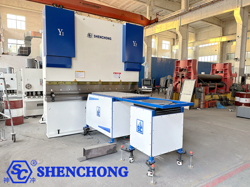
Focus on preventing the sheet metal’s own weight from causing sagging, bending line deviation, or unnecessary scratches on the surface. 1) Support positions and follow-up trajectories should be set appropriately.
2) Bending of large heavy plates
Prioritize calculating the weight of the plate, center of gravity, support reaction force, and eccentric load. The material support device may not be able to bear the full weight of the workpiece; if necessary, additional hoisting or support schemes confirmed by the engineering team should be adopted.
3) Box bodies and multiple bends
Focus on checking whether the bent edges, side-flanged edges, and protrusions interfere with the material support platform, support arms, and frame. Adjust the bending sequence if necessary.
4) Aluminum plates and decorative panels
Prioritize using clean material support surfaces, ball bearings, or protective materials suitable for the workpiece surface, and check for metal shavings, sharp edges, and foreign objects to reduce the risk of scratches.
8. Common Faults and Troubleshooting Methods
Fault Symptoms | Possible causes | Troubleshooting Directions |
Follow-up device fails to start | Power supply malfunction, emergency stop not reset, starting conditions not met | Check power supply, alarms, and safety status |
Material platform does not follow | Sensor no signal, communication failure, incorrect control mode | Check feedback signals, communication status, and mode |
Follow-up direction is reversed | Direction configuration error or abnormal parameters | After shutdown, check the directional configuration according to the manufacturer’s procedures |
Significant delay in movement | Feedback malfunction, trajectory parameter mismatch, excessive mechanical resistance | Check signals, parameters, and mechanical motion status |
Platform vibration or abnormal noise | Loose connection, transmission wear, mechanism jamming | After shutdown and power deprivation, check the mechanical structure |
Servo overload alarm | Overload, mechanical interference, abnormal transmission resistance | Eliminate interference and verify load and drive status |
Incorrect origin position | Reference point offset, loose sensor or parameter changes | Re-execute the prescribed calibration procedure |
Workpiece surface scratches | Foreign objects, burrs, or improper contact on the material support surface | Clean the material support surface and check the contact area |
Unstable bending angle | Inconsistent sheet metal support, material differences, or process deviations | Check the support, mold, plate thickness, and bending procedure |
Incomplete return stroke | Abnormal limit switches, obstacles, or incorrect program parameters | Stop automatic operation and check stroke and feedback |
Standard troubleshooting sequence:
- Stop current operation and bring dangerous movements to a safe state according to equipment specifications.
- If internal mechanisms or wiring need inspection, perform the prescribed energy isolation, lockout and tagging, and confirm that residual energy has been safely released.
- Record alarm codes, the step in which the fault occurred, workpiece information, and any abnormal phenomena.
- Inspect according to the fault list; repairs beyond the operator’s authority should be performed by qualified personnel.
- After troubleshooting, re-check safety functions and perform the prescribed no-load test and sample verification before resuming production.
9. Maintenance Plan
Maintenance cycles should be determined based on equipment usage frequency, working environment, load conditions, and manufacturer requirements. The table below provides a suggested daily maintenance framework and does not represent mandatory cycles for all models.
Cycle | Maintenance Contents | Inspection Standards |
Per shift | Clean the material support surface; inspect appearance, alarms, and movement status | No foreign objects, no abnormal noises |
Weekly | Inspect connectors, caster brakes, cables, and sensor fixation | No looseness, wear, or damage |
Monthly | Check repeatability, limit actions, and clearances | Meets the allowable deviations specified by the equipment |
As per manufacturer’s schedule | Inspect transmission components, lubrication points, bearings, and reduction gear | Lubrication and wear conditions meet requirements |
Regular professional maintenance | Inspect the electrical system, drive, grounding, and safety functions | Test results meet equipment specifications |
After abnormal repairs | Recheck mechanical position, feedback, interlocks, and follow-up trajectory | Production can only resume after verification and approval |
1) Lubrication and Cleaning
Use the specified grade of lubricant only at the locations designated by the manufacturer.
Do not spray cleaning agents onto servo motors, encoders, or electrical components indiscriminately.
Clean metal shavings, oil stains, and sharp foreign objects from the material support platform.
Address any issues such as insufficient lubrication, oil leaks, wear, or abnormal temperature rise promptly.
2) Sensors and Control System
Check the position sensors and their supports for looseness.
Check the magnetic scale, connectors, and signal cables for impact damage or contamination.
Back up controller parameters and equipment configuration.
Do not upgrade software, modify driver parameters, or restore factory settings arbitrarily.
3) Restarting After Long-Term Shutdown
After a long-term shutdown, check the mechanical structure, power supply, lubrication, sensors, and safety functions.
When restarting, first complete the zeroing and no-load test run as specified by the manufacturer before performing test piece bending. Do not directly resume full-load production.
10. Common Questions about Follow-up Material Support Devices (FAQ)
Q1: Can a bending follow-up material support device improve bending accuracy?
It can improve processing stability under certain conditions. It helps improve workpiece consistency by supporting the sheet metal, reducing sagging and positional deviation. However, the final accuracy is still affected by the bending machine’s condition, die, material differences, compensation parameters, and operating procedures.
Q2: Is the follow-up material support device suitable for all bending machines?
No. It’s necessary to confirm the machine’s installation space, the material support device’s load-bearing capacity, range of motion, control interface, and safety interlocks. Some equipment requires dedicated brackets or manufacturer modification solutions.
Q3: Can the follow-up material support device completely replace manual labor?
Not necessarily. It can reduce manual lifting and auxiliary support work, but the safety management of loading, positioning, flipping, picking up, and complex workpieces still depends on the equipment configuration and level of automation.
Q4: What should I do if the material support arm vibrates during operation?
The relevant processing should be stopped, and the machine should be checked for loose mechanisms, motion interference, guide rail contamination, transmission wear, or control abnormalities. Do not directly increase the speed or arbitrarily modify the servo gain to mask the problem.
Q5: How to avoid scratching the surface of stainless steel sheets?
Keep the support surface clean, remove metal shavings and burrs, select appropriate protective measures for the workpiece surface, and check the sliding and contact of the sheet metal during the follow-up process.
Q6: How often is maintenance required?
The maintenance cycle specified by the manufacturer should be followed. Cleaning and visual inspection can usually be incorporated into each shift’s work, while checks of the transmission mechanism, fasteners, and position status should be included in periodic maintenance, with the schedule adjusted according to operating intensity.
Q7: Can the follow-up material support device be integrated into the robot bending workstation?
Some models can, but it requires comprehensive consideration of the robot’s motion range, material support arm trajectory, workpiece gripping position, control communication, and safety interlocks, and must undergo system-level risk assessment and debugging.
11. Manual Summary: Core Principles of Correct Use
The effective use of the CNC press brake bending follower device can be summarized into six core tasks:
- Correct Selection: The equipment structure, load-bearing capacity, and control method are matched with the workpiece and bending machine.
- Installation Specifications: The installation position, mechanical connection, zero point, and limit switches all meet the manufacturer’s requirements.
- Program Matching: Sheet parameters, bending sequence, and material support trajectory have been verified.
- Stable Operation: The material support arm moves in coordination with the sheet material, without abnormal pushing, slippage, or collision.
- Timely Maintenance: Regular inspections are conducted on the motion mechanism, control system, support surface, and safety functions.
- Safety First: Any abnormality is handled according to regulations, and production is not continued without the shielding protection function.

 English
  Spanish
  Portuguese
  Russian
  Arabic
  French
  Italian
  German
  Polish
  Thai
Thai  Vietnamese
  Lithuanian
  Czech
Czech  Korean
  Japanese
  Chinese