
Table of Contents
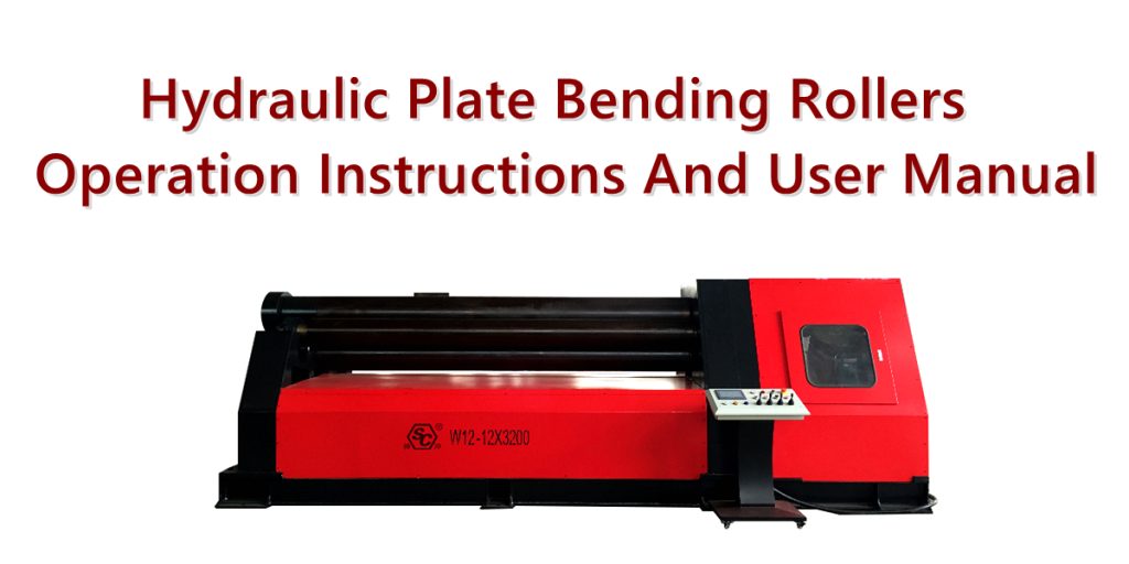
Hydraulic plate bending rollers are essential equipment in metal sheet forming and processing. They primarily utilize the relative position and rotational movement of the upper, lower, and side rollers to continuously bend metal sheets such as steel, stainless steel, and aluminum, gradually shaping flat sheets into cylindrical, arc-shaped, conical, and other curved workpieces.
Different structures of hydraulic plate rolling machines have different operating methods, especially three-roll, four-roll, symmetrical, asymmetrical, and CNC hydraulic plate bending machines, whose roller movements and control methods are not entirely the same. Therefore, the following content is based on common hydraulic three-roll/four-roll plate rolling machines.
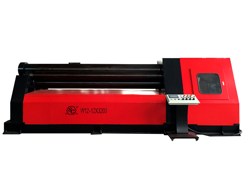
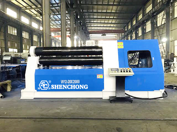
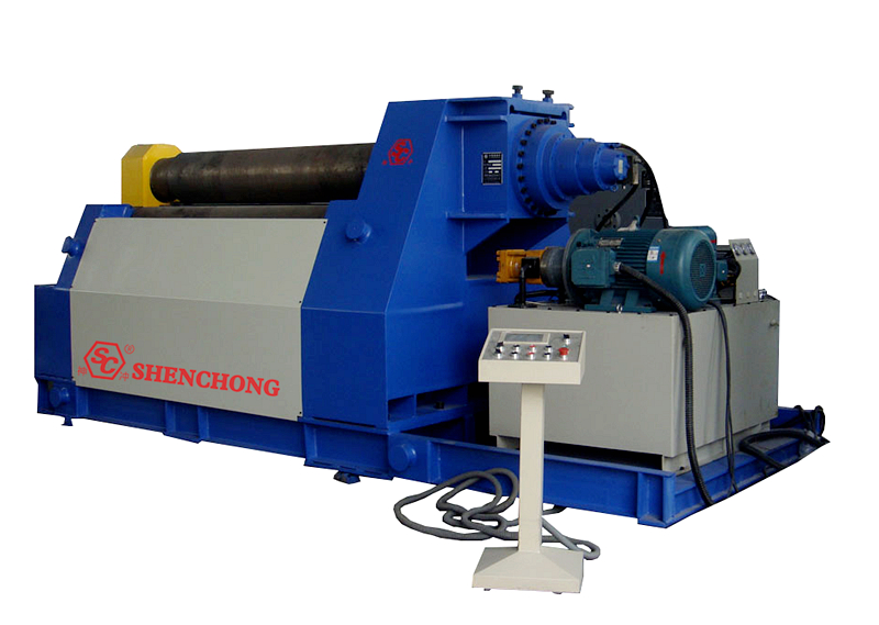
Actual operation must be based on the instruction manual, hydraulic schematic diagram, and electrical drawings provided by the equipment manufacturer. Four-roll machines typically consist of an upper roller, a lower roller, and left and right side rollers. The lower and side rollers are raised and lowered by hydraulic cylinders, and the control system is responsible for the actions of each mechanism.
1. Basic Structure Of Hydraulic Plate Bending Rollers
A typical hydraulic plate rolling machine mainly includes the following systems:
System | Main Components | Main functions |
Frame system | Left and right frames, base, connecting beams | Bear the main load during the sheet rolling process |
Roller system | Upper roller, lower roller, side rollers | Apply bending pressure to the sheet material |
Main drive system | Hydraulic motor/electric motor, reducer, gears, etc. | Drive the rollers to rotate |
Hydraulic system | Hydraulic pump, oil tank, valve group, cylinder, pipelines | Achieve roller lifting, clamping, and tilting |
Electrical system | Electrical control cabinet, PLC, contactors, sensors | Control equipment operation |
Operating system | Button station, touch screen or CNC system | Human-machine interaction and parameter setting |
Tilting device | Tilting cylinder, tilting frame | Facilitate removal of the forming cylinder |
Balancing/synchronizing device | Synchronization valve, displacement sensor, etc. | Ensure consistent movement at both ends of the rollers |
Safety device | Emergency stop, limit switch, guardrail, safety rope, etc. | Prevent personnel from accidentally entering hazardous areas |
In a typical structure of a four-roll hydraulic plate bending machine, the upper roll usually undertakes the main driving and bending functions, the lower roll is used to clamp the plate, and the two side rolls are used for end pre-bending and overall forming.
2. Essential Knowledge Operators Must Master
Before commencing operation, operators should be familiar with:
- Machine structure
- Hydraulic system working principle
- Electrical control button functions
- Movement direction of each roller
- Maximum permissible sheet thickness
- Maximum permissible sheet width
- Minimum rolling diameter
- Maximum rolling capacity
- Material strength limitations
- Maximum permissible working pressure
- All hazardous areas
- Emergency stop button location
- Correct loading and unloading methods
- Workpiece unloading methods
- Shutdown procedures in abnormal situations
Personnel who have not been trained or are unfamiliar with the equipment’s operation should not operate the plate rolling machine independently.
One of the greatest safety risks of the plate rolling machine comes from the pinching area between the rotating rollers. Therefore, handles, clothing, tools, etc., must always be kept away from the roller system during operation. Relevant equipment manuals also list the rotating roller area as a critical hazardous area.
3. Standard Operating Procedure for Hydraulic Plate Rolling Machine
When training operators, the following procedure can be followed directly:
① Check the equipment
↓
② Check the hydraulic oil
↓
③ Check the lubrication
↓
④ Check the electrical system
↓
⑤ Check the emergency stop and safety devices
↓
⑥ Start the hydraulic pump
↓
⑦ Check the movement of each roller under no-load conditions
↓
⑧ Confirm the plate specifications
↓
⑨ Load the plate
↓
⑩ Center the plate
↓
⑪ Clamp the lower roller
↓
⑫ Pre-bend the first end
↓
⑬ Change direction
↓
⑭ Pre-bend the second end
↓
⑮ Roll the middle section
↓
⑯ Round the plate after multiple passes
↓
⑰ Dimensional inspection
↓
⑱ Meets requirements
↓
⑲ Release the workpiece
↓
⑳ Tilting/unloading
↓
㉑ Clean the equipment
↓
㉒ Check the equipment
↓
㉓ Stop the machine and disconnect the power
4. Pre-start Inspection
Pre-start inspection is a crucial step in operating a hydraulic plate bending roller machine.
1) Mechanical Component Inspection
Inspect:
- Check for cracks in the frame.
- Check for loose connecting bolts.
- Check for obvious damage to the roller surfaces.
- Check for foreign objects on the upper, lower, and side rollers.
- Check for normal gear operation.
- Check for loose couplings.
- Check for abnormal bearings.
- Check for proper functioning of the tilting device.
- Check the reliability of all limit devices.
- Pay special attention to the roller surfaces.
Severe pitting, scratches, or localized deformation on the roller surfaces can cause indentations on the plate surface and affect the roundness of the rolled material.
2) Hydraulic System Inspection
The hydraulic system is the primary power source for the hydraulic plate rolling machine.
Key pre-start checks:
① Hydraulic Oil Level
Check the oil level gauge in the tank.
A low oil level may cause:
- Hydraulic pump cavitation
- Unstable system pressure
- Increased hydraulic oil temperature
- Abnormal actuator operation
- Damage to the hydraulic pump
A high oil level is also unreasonable; the oil level should be checked according to the manufacturer’s specifications.
② Hydraulic Oil Condition
Observation:
- Is it emulsified?
- Is it noticeably darkened?
- Does it contain a large amount of impurities?
- Does it have abnormal bubbles?
- Does it have a noticeable odor?
Hydraulic oil contamination directly affects the reliability of hydraulic valves, pumps, and cylinders.
③ Piping Inspection
Inspect:
- High-pressure oil pipes
- Connectors
- Valve blocks
- Cylinders
- Sealing parts
Confirm there are no obvious oil leaks.
④ Pressure Gauge
Inspect the pressure gauge:
- Is it at zero normally?
- Is the pointer stuck?
- Is the surface damaged?
- Is the pressure display abnormal?
Do not arbitrarily increase the system pressure to improve rolling capacity.
The maximum allowable pressure of the equipment is determined by the hydraulic system, cylinders, frame, bearings, and rollers.
3) Lubrication System Inspection
The bearings, gears, guide rails, and sliding parts of the plate rolling machine need to be lubricated according to equipment requirements.
Common lubication locations include:
- Roller bearings
- Tilting device
- Guide rails
- Gears
- Reducer
- Sliding bearings
- Related moving parts of hydraulic mechanisms
Proper lubrication can reduce friction and wear, and improve equipment lifespan. Some plate rolling machine manuals recommend establishing a periodic lubrication schedule based on equipment load and operating conditions.
Note:
Grease and lubricating oil should not be mixed arbitrarily; selection should be based on the equipment manufacturer’s requirements.
4) Electrical System Inspection
Pre-start checks:
- Power supply voltage
- Grounding
- Electrical control cabinet
- PLC
- Operating buttons
- Emergency stop button
- Limit switches
- Travel switches
- Sensors
- Motor
- Hydraulic pump motor
- Control circuit
Especially important to confirm:
The emergency stop button can normally cut off equipment operation.
Some plate rolling machines are equipped with phase sequence protection to prevent motor reverse rotation from causing hydraulic pump malfunction.
5. Start-up Operation Procedures
Step 1: Clear the Work Area
Ensure there are no:
Sheet metal, tools, bolts, welding rods, lifting equipment, personnel, or other obstacles around the plate rolling machine.
Step 2: Connect the Main Power
Turn on the main power supply.
Observe:
Power indicator light, PLC, touch screen, and all alarm messages.
If a fault alarm occurs, first determine the cause; do not force a restart.
Step 3: Start-up hydraulic plate bending roller
Start the hydraulic pump station.
Do not immediately perform full-load plate rolling upon startup.
For some four-roll hydraulic bending rollers, the manufacturer’s operation manual requires that after a long period of shutdown, the oil pump should be run for a period of time before restarting to allow the hydraulic system to fully establish normal operating conditions. The specific time should be followed according to the machine’s instruction manual.
6. No-load Test Run
A no-load test should be conducted before formal processing.
Check in sequence:
1) Lower Roller Lifting
Observe:
Is the lifting smooth?
Is the descent smooth?
Are the left and right ends synchronized?
Are there any abnormal sounds?
2) Side Roller Lifting
Check the left and right side rollers respectively.
Confirm:
- Correct direction of movement
- Smooth lifting
- Synchronized at both ends
- Limit switches functioning normally.
3) Main Roller Forward and Reverse Rotation
Test:
- Forward Rotation
- Reverse Rotation
- Stop
Confirm that the rotation direction is consistent with the operation button.
4) Tilting Device
Check:
- Tilting
- Reset
- Lock
The tilting device must be operated under specified conditions.
It is forbidden to operate the tilting device while the main roller is rotating at high speed.
7. Sheet Metal Preparation
Before formally rolling the sheet metal, the sheet metal parameters should be confirmed.
At least the following should be known:
- Material
- Material Yield Strength
- Thickness
- Width
- Length
- Target Diameter
- Rolling Direction
- Whether Pre-bending is Required
- Whether Tapering is Required
Common Materials:
For example:
- Carbon Steel
Q235, Q355, etc.
- Stainless Steel
304, 316L, etc.
- Aluminum Plate
5052, 6061, etc.
Different materials have different strengths, elongations, and springbacks.
Therefore: For Q235 and 304 stainless steel of the same thickness and width, the rolling parameters cannot be simply copied.
8. Sheet Metal Inspection
Before formally rolling the sheet metal, the following should be checked:
- Whether the thickness is uniform
- Whether the width meets the requirements
- Whether there is severe deformation
- Whether there are cracks
- Whether there are burrs
- Whether there are foreign objects on the surface
The sheet metal should be as flat as possible.
Sending severely uneven sheet metal directly into the plate rolling machine will cause:
- Sheet metal misalignment
- Oval roll shape
- Inconsistent end shapes
- Abnormal localized stress
9. Sheet Alignment
Sheet alignment is crucial.
Theoretically:
The centerline of the sheet should correspond correctly with the centerline of the rollers on the rolling machine.
If the sheet is off-center, the following may occur:
- Different rolling radii on the left and right ends
- The cylinder will be conical
- Sheet misalignment
- Uneven roller stress
- Product dimensions will be out of tolerance
Therefore, after loading, do not rush to roll the sheet. First, complete the positioning and alignment.
10. Standard Rolling Operation Procedure For 4-Roll Hydraulic Plate Rolling Machine
For a common four-roll hydraulic plate bending roller machine, a complete rolling process can be understood as:
Feeding → Centering → Clamping → End Pre-bending → Reversal → Other End Pre-bending → Middle Rolling → Multiple Rounding → Forming → Unloading
1) First End Pre-bending
After the plate is positioned, it is clamped between the upper and lower rollers by the lower roller.
Then:
- Start the upper roller
- Slowly rotate the plate
- Adjust the side roller position
- Pre-bend the end of the plate
Stop after meeting the process requirements
The main purpose of pre-bending is to reduce straight edges. If the pre-bending is insufficient, obvious straight sections may appear at both ends of the final cylinder.
2) Second End Pre-bending
After completing the first end pre-bending:
- Maintain proper clamping with the lower roller
- Reverse rotation of the upper roller
- Return the plate
- Adjust the other side roller
- Pre-bend the other end
The four-roll machine can easily perform double-end pre-bending, which is one of its important advantages over some traditional three-roll structures.
3) Intermediate Rolling
After pre-bending at both ends, begin rolling the middle section of the sheet.
Basic Process:
Adjust side rollers → Start main roller → Sheet advances → Adjust side rollers → Continue rolling → Repeat cycle
In actual production, the sheet cannot usually be rolled to the final diameter in one go.
Instead, it should be:
Gradually apply pressure, gradually shape, and roll back and forth multiple times.
This is more conducive to controlling:
- Roundness
- Diameter
- Residual stress
- Sheet deviation
- Roller stress
11. Basic Control Methods For Rolling Cylinder
If the goal is to roll a cylinder:
- Stage 1: Lightly press the sheet material to create an initial curvature.
- Stage 2: Gradually increase the pressure from the side rollers.
- Stage 3: Continue rotating and adjusting the roller positions.
- Stage 4: Perform multiple reciprocating rolls.
- Stage 5: Reduce the adjustment amount as you approach the target diameter.
- Stage 6: Perform final rounding.
Avoid excessive roller position adjustments in the final stage.
12. How to determine if the diameter is close to the target diameter during the rolling process?
It can be determined using:
- Sample
- Outer diameter measurement
- Inner diameter measurement
- CNC position display on the rolling machine
- Laser measurement
- Calipers
- Measurement tape
- Dedicated arc template
For high-precision production, visual inspection alone is insufficient.
13. Why are multiple rolling processes necessary?
Because sheet metal has elasticity and plasticity.
When the external force is removed:
- Elastic deformation recovers
- The material springs back
- The actual radius may increase.
Therefore:
Reaching a certain position on the roller does not mean the sheet metal will ultimately maintain that radius. This springback issue is particularly pronounced with materials like high-strength steel and stainless steel.
Therefore, production typically requires:
Rough rolling → Medium rolling → Fine rolling → Rounding
14. Important Safety Regulations During Plate Rolling
The following situations must be given high priority.
1) Never put your hands between the rollers
This is one of the most important safety regulations.
Do not use your hands to:
- Hold the plate
- Push the plate
- Pull the plate
- Clean the plate
- Adjust the plate edges
Especially during roller rotation.
2) Never stand in the direction of plate movement
The plate may suddenly:
- Slip
- Roll up
- Pop up
- Shift
- Obstruction
Operators should stand in the designated safe area.
3) Never roll plates beyond their specifications
For example, if the equipment’s rated capacity is 16 × 2000 mm, this does not mean that all materials can be directly rolled to 16 mm × 2000 mm.
The following also need to be considered:
- Material strength
- Yield strength
- Minimum roll diameter
- Effective roll width
- Plate condition
- Rolling method
15. Prohibited: Correcting Severely Uneven Sheet Metal
Do not use a plate rolling machine as a regular press.
If the plate is severely deformed, appropriate leveling equipment should be used.
Forced correction may result in:
- Excessive stress on the rollers
- Frame deformation
- Bearing damage
- Hydraulic system overpressure
- Local deformation of the plate
16. Conical Operation
If the equipment supports conical operation, the left and right rollers need to have an appropriate height or position difference.
Special attention should be paid to the following during conical operation:
- Plate centering
- Right and left roller positions
- Side direction of the small and large ends of the cone
- Plate width
- Cone angle
- Minimum rolling diameter
- Allowable roller offset
The stress state during conical operation differs from that of ordinary cylindrical rolling.
Therefore:
Conical operation cannot be performed simply according to the parameters of ordinary cylindrical rolling.
For CNC plate rolling machines, the conical calculation program or process parameters provided by the manufacturer should be used preferentially.
17. Unloading after Forming
After rolling is completed, do not immediately forcibly lift the workpiece away.
The correct procedure typically includes:
- Stop the main roller rotation
- Adjust the roller to the unloading position
- Loosen the clamps
- Operate the tilting device according to the equipment structure
- Open the upper roller end
- Use a lifting device to lift the cylinder out
- Reset the tilting device
- Reset the upper roller
- Check the equipment status
Four-roll plate bending machines are usually equipped with a tilting device to allow the formed cylinder to be removed from the roller end.
18. Precautions for Lifting Workpieces
The rolled cylinder is often quite heavy.
The following must be used:
- Overhead crane
- Crane
- Qualified lifting slings
- Hook
- Special lifting equipment
Pre-lift inspection:
- Sling rated load
- Lifting points
- Workpiece stability
- Center of gravity
- Wear condition of lifting equipment
Personnel are prohibited from standing on:
- Under the workpiece
- Within the workpiece’s rotation range
- Under the lifting path
19. Shutdown Procedure
After production is completed, the machine should be shut down according to specifications.
General procedure:
Stop rolling → Rollers stop → Rollers return to safe position → Clean equipment → Check hydraulic system → Turn off hydraulic pump → Turn off control power → Turn off main power
After the equipment stops, the following should also be checked:
- Oil leaks
- Abnormal overheating
- Abnormal noises
- Loose parts
- Sheet metal debris
- Metal oxide buildup
20. Daily Maintenance
Per-shift Maintenance
Recommended Inspections:
- Hydraulic oil level
- Hydraulic lines
- Hydraulic cylinders
- Pressure gauges
- Rollers
- Bearings
- Gears
- Motors
- Limit switches
- Emergency stops
- Lubrication points
Weekly Maintenance
Inspections:
- Electrical control cabinet
- Terminal blocks
- Cables
- Hydraulic valves
- Hole fittings
- Gear meshing
- Guide rails
- Tilting device
- Mechanical connections
Monthly Maintenance
Recommended Inspections:
- Hydraulic system pressure
- Hydraulic oil contamination level
- Oil tank
- Filter
- Bearings
- Roller parallelism
- Roller wear
- Frame connecting bolts
21. Common Operational Errors of Hydraulic Plate Rolling Machines
Error 1: Rolling directly without centering
Consequences:
- Conical shape
- Oval shape
- Uneven roller load
Error 2: Pressing too deeply in one go
Consequences:
- Sudden increase in roller stress
- Local plastic deformation of the plate
- Excessive equipment load
Error 3: Rolling without pre-bending
Consequences:
- Significant straight edges at both ends
- Reduced finished product utilization
- Difficulty in subsequent welding
Error 4: Ignoring material strength
The rolling difficulty of Q235 and high-strength steel may be completely different for the same 10 mm plate.
Error 5: Ignoring springback
Directly forming according to the theoretical dimensions in one go easily results in a final diameter that is too large.
Error 6: Overloading the equipment
Overloading may cause:
- Permanent deformation of the roller
- Frame deformation
- Damage to the hydraulic system
- Bearing damage
22. Operating Techniques to Improve Plate Rolling Accuracy
1) Ensure Plate Centering
This is the most basic and crucial condition.
2) Perform Proper End Pre-bending
Insufficient pre-bending will result in excessively large straight edges.
3) Use Multi-Pass Rolling
Don’t aim for “one-pass accuracy.”
4) Gradually Approach the Final Dimension
After rough rolling, perform fine rolling.
5) Control the Consistency of Left and Right Roller Positions
Especially for cylindrical rolling.
6) Consider Material Springback
High-strength materials and stainless steel require particular attention.
7) Final Rounding
If necessary, perform rounding through multiple back-and-forth rotations.
23. Core Operating Rules for Plate Rolling Machines
Daily operations can be condensed into the following set of rules:
- Check before starting, confirm hydraulics first.
- Plate must be centered, rollers must be parallel.
- Clamping should not be excessive, pre-bending is mandatory.
- Rough rolling in multiple passes, fine rolling with slow adjustments.
- Overload is unacceptable, stop immediately if abnormality occurs.
- Keep hands away from the rotating area and avoid hazards during hoisting.
- Clean up before finishing work, and disconnect power only after stopping the machine.
24. Summary
The core of correctly operating a hydraulic plate bending roller machine is not simply “making the rollers rotate,” but rather simultaneously controlling plate positioning, clamping force, side roller position, rolling speed, pre-bending amount, material springback, and final rounding.
For four-roll hydraulic plate rolling machines, the correct operating sequence is especially important. Its structure allows for relatively convenient double-end pre-bending and continuous forming, but the specific roller positions and pressures must be determined based on the equipment model, plate thickness, material, and target diameter.
- Before starting: Check electrical systems → Check hydraulic systems → Check lubrication → Check rollers → Check safety devices
- Starting: Main power supply → Hydraulic pump → No-load operation → Confirm normal operation
- Loading: Confirm sheet material → Center → Position → Clamp
- Rolling: First end pre-bend → Second end pre-bend → Intermediate rolling → Multiple rounding adjustments
- Inspection: Measure diameter → Measure roundness → Check straight edges → Inspect surface
- Unloading: Stop rollers → Release clamps → Tilting → Lifting
- Shutting down: Clean → Inspect → Stop hydraulic pump → Turn off power
 English
  Spanish
  Portuguese
  Russian
  Arabic
  French
  Italian
  German
  Polish
  Thai
Thai  Vietnamese
  Lithuanian
  Czech
Czech  Korean
  Japanese
  Chinese