

Table of Contents
Metal laser cutting is a process that may appear as simple as “setting the parameters and cutting,” but in reality, it involves a multitude of factors: laser power, focal position, nozzle, assist gas, gas pressure, cutting speed, material type, thickness, surface condition, optical path, lenses, cooling system, and machine motion accuracy.
This is particularly true for fiber laser cutting machines. As power levels have evolved from 3kW, 6kW, and 12kW to 20kW, 30kW, and beyond, simply increasing power does not guarantee cutting quality. Achieving truly high-quality, high-efficiency cutting requires establishing a comprehensive process system that integrates material, power, focal point, nozzle, gas, speed, pressure, and cutting path.
The following is a systematic summary of sheet metal laser cutting techniques from a practical production perspective.
1. Core Logic of Sheet Metal Laser Cutting
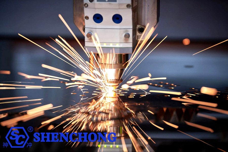
At its core, laser cutting utilizes a high-energy-density laser beam to rapidly melt, vaporize, or ignite the material locally, while simultaneously using assist gas to expel the molten material from the kerf (the cut gap).
A complete cutting process can be broken down as follows:
Laser generator → Beam transmission → Focusing → Material heating → Melting/Vaporization → Assist gas slag removal → Kerf formation
Consequently, cutting quality ultimately depends on several core variables:
Laser energy density + Focal state + Material response + Gas slag removal capability + Motion trajectory
Issues in any of these areas can lead to:
- Burrs
- Dross adhesion
- Incomplete cutting
- Excessive kerf width
- Beveled edges
- Edge burning
- Over-burning
- Hole deformation
- Non-circular holes
- Dimensional errors
- Surface blackening
- Reduced cutting speed
- Lens contamination
- Nozzle damage
2. Critical Preparations Before Cutting
Many cutting defects do not stem from parameter settings but rather from issues present before the actual cutting process begins.
1) Inspecting the Sheet Material
Before cutting, check the following:
- Is the sheet thickness accurate?
- Does the material type match the program specifications?
- Is the sheet flat?
- Is there severe surface rust?
- Is there oil or grease contamination?
- Is there mill scale?
- Are there scratches?
- Is there localized deformation?
- Does the sheet contain internal stress?
This is particularly important for thin sheets. If the sheet itself is severely warped, achieving consistent cutting results is difficult, even with a laser head equipped with automatic focusing.
2) Recommendations
For high-precision parts:
Prioritize the use of sheets with good flatness.
For thick plates:
Pay special attention to internal stress and thermal deformation.
3. Cutting Techniques for Different Metal Materials
Different materials respond quite differently to laser energy and assist gases.
1) Carbon Steel
Carbon steel is one of the most common materials for laser cutting.
Common thicknesses:
0.5mm
1mm
1.5mm
2mm
3mm
4mm
5mm
6mm
8mm
10mm
12mm
16mm
20mm
25mm
30mm and above
Thin carbon steel: Thin sheets can generally be cut using air, oxygen, or nitrogen.
Advantages of oxygen cutting:
- High cutting capacity
- Good performance on thick plates
- Relatively low cost
However, since oxygen participates in the oxidation reaction, an oxide layer forms on the cut edge.
2) Stainless Steel
Stainless steel is generally better suited for nitrogen cutting.
This is because nitrogen minimizes oxidation at the cut edge.
Advantages:
- Better edge color
- Brighter cut surface
- Reduced oxidation
- Suitable for subsequent welding
- Suitable for processing parts where appearance matters
Advantages:
- Better edge color
- Brighter cut surface
- Reduced oxidation
- Suitable for subsequent welding
- Suitable for processing parts where appearance matters
3) Aluminum Sheets
Aluminum is a material with high reflectivity and high thermal conductivity.
When cutting aluminum sheets, special attention must be paid to:
- Laser reflection
- Focal position
- Piercing stability
- Nozzle height
- Assist gas
- Material surface condition
Cutting difficulty increases significantly, especially with thick aluminum plates.
4) Brass and Copper
One of the biggest challenges with copper and brass is their high reflectivity.
Processing copper—especially with traditional-wavelength fiber laser systems—places higher demands on the laser source, cutting head, and process parameters.
In actual production, pay special attention to:
- Whether the equipment supports highly reflective materials
- Whether the laser source is suitable for copper
- Piercing stability
- Nozzle compatibility
- Cleanliness of the protective lens
Do not simply apply standard parameters used for carbon steel.
4. Higher laser power not always better
Many users fall into a common misconception when selecting a laser cutting machine:
The higher the power, the better the cutting performance.
In reality, this is not the case.
For example, with 6kW, 12kW, or 20kW systems:
The advantages primarily lie in:
- Ability to cut thicker materials
- Higher cutting speeds
- Greater production efficiency
- A wider process window
However, when cutting:
Thin sheets (1mm, 2mm, 3mm)
High power does not necessarily translate directly into superior cutting quality.
For thin sheets, high power can even lead to issues such as:
- Over-burning
- Deformation of small holes
- Edge melting
- An enlarged heat-affected zone (HAZ)
Therefore, equipment selection should follow this principle:
Choose the power level based on the material type, thickness range, and production cycle requirements, rather than simply pursuing the highest possible power.
5. Focal position key to cutting quality
The focal position is one of the most critical parameters in the laser cutting process.
Simply put:
The focal position determines how laser energy is distributed across the thickness of the sheet.
If the focus is too high or too low, cutting performance will be affected.
1) Thin sheets
Thin sheets generally require a high concentration of energy.
If the focus deviates significantly, it can lead to:
- Widened kerf (cut width)
- Incomplete cutting (failure to cut through)
- Increased burrs
- Reduced cut quality
2) Thick plates
Cutting thick plates requires consideration of how laser energy is distributed within the material.
Adjustments to the focal position generally need to be made based on a combination of factors:
- Material
- Thickness
- Laser power
- Nozzle type
- Gas pressure
- Cutting speed
3) Do not rely blindly on a fixed focal position
The optimal focal position varies depending on the material, thickness, and gas used.
Therefore, actual production operations should establish a system linking:
Material + Thickness + Gas + Power → Corresponding focal parameters
This helps build the company’s own proprietary process database.
6. Nozzle selection is crucial
Although the nozzle is a small component, it has a significant impact on cutting quality.
Common nozzle types include:
- Single-layer nozzles
- Double-layer nozzles
Nozzles with various orifice diameters For example:
1.0mm
1.2mm
1.5mm
1.8mm
2.0mm
2.5mm
3.0mm
The actual selection cannot be based solely on material thickness.
Other factors must also be considered:
- Laser power
- Assist gas
- Gas pressure
- Cutting speed
- Material
- Nozzle structure
The nozzle must be accurately centered.
This is an issue that is often overlooked.
If the laser beam is not accurately centered within the nozzle:
It can result in:
- Dross accumulation on one side
- Slanted cut edges
- Unstable cutting
- Nozzle collisions
- Piercing irregularities
Therefore, regularly checking:
Nozzle concentricityis crucial.
7. Tips for Selecting Assist Gas
Assist gas does more than just “blow away the molten slag.”
It actually plays a role in:
- Slag removal
- Cooling
- Oxidation reactions
- Cutting speed control
- Cut quality control
Common gases:
Oxygen (O₂)
Primarily used for cutting carbon steel.
Advantages:
- Strong cutting capability
- Good performance on thick plates
- Low cost
Disadvantages:
- Oxidation layer forms on the cut edge
Nitrogen (N₂)
Primarily used for:
- Stainless steel
- Aluminum
- Copper
- High-quality aesthetic parts
Advantages:
- Minimal oxidation on the cut edge
- Better cut surface appearance
- Suitable for subsequent welding and surface treatment
Disadvantages:
- Higher gas cost
- Thick plate cutting requires high gas pressure and equipment capability
Compressed Air
Air cutting has become increasingly popular in recent years.
Advantages:
- Low cost
- Easily accessible
- Very economical for processing certain thin sheets
However, since air contains oxygen and moisture, attention must be paid to:
Air compressor + dryer + filtration system
Excessive moisture content in the air can compromise cutting stability and increase the risk of contaminating related components.
8. How to Adjust Cutting Speed?
Cutting speed is a critical parameter.
1) Speed is too fast
Potential issues:
- Incomplete penetration
- Dross adhesion at the bottom
- Incomplete cut seam
- Failure to cut through sharp corners
- Reduced quality of small holes
2) Speed is too slow
Potential issues:
- Over-burning
- Increased heat-affected zone (HAZ)
- Widened cut kerf
- Plate deformation
- Blackened edges
- Increased dross adhesion
Therefore, the correct mindset is not “the faster, the better.”
Instead, the goal is to maximize stable cutting speed while ensuring full penetration and high cut quality.
9. How do you determine if the cutting speed is appropriate?
You can observe the cutting sparks.
1) Normal state
Sparks:
- Discharged smoothly
- Stable direction
- No significant upward back-spray
- Continuous cut line
2) Speed too fast
Typically observed:
- Sparks trail significantly backward
- Difficulty discharging slag from the bottom
- Incomplete cutting in some areas
3) Speed too slow
May result in:
- Expanded molten zone
- Abnormally concentrated sparks
- Overheating of the plate edge
This is a very practical method for on-site assessment.
10. Piercing techniques
Piercing is often one of the stages in laser cutting most prone to issues.
Especially with:
Thick plates, highly reflective materials, and special materials
Piercing is more difficult.
1) Do not use standard cutting parameters for piercing
Piercing conditions differ from continuous cutting conditions.
Separate settings are usually required for:
- Piercing power
- Piercing time
- Piercing gas pressure
- Piercing focal position
- Number of piercing pulses
- Piercing height
2) Multi-stage piercing is recommended for thick plates
For thick plates, you can use:
Low-energy pre-piercing → High-energy penetration
Or multi-stage piercing.
This helps reduce:
- Spatter
- Lens contamination
- Nozzle damage
- Piercing failure
11. Small-hole cutting techniques
This is a crucial technique in actual production.
Example: 6mm plate thickness, 6mm hole diameter
Cutting such small holes is significantly more difficult than cutting standard contours.
Generally speaking:
The closer the hole diameter is to the plate thickness, the more difficult the cut.
For small-hole processing, focus on adjusting:
- Laser power
- Speed
- Focal position
- Gas pressure
- Piercing parameters
- Lead-in line
- Cornering speed
Do not simply copy parameters used for outer contours.
12. Why do small holes often turn out elliptical?
Common causes include:
1) Cutting speed too fast
Lorem ipsum dolor sit amet, consectetur adipiscing elit. Ut elit tellus, luctus nec ullamcorper mattis, pulvinar dapibus leo.
2) Acceleration too high
The mechanical system changes direction frequently within the small circle.
3) Laser power too high
Can easily cause localized heat accumulation.
4) Inappropriate gas pressure
Insufficient slag removal capability. 5) Inaccurate focus
This results in uneven energy distribution on both sides of the kerf.
5) Insufficient machine motion accuracy
Specifically regarding:
- Racks
- Gears
- Guide rails
- Servo systems
Errors in these components will affect the roundness of small holes.
13. Sharp Corner Cutting Techniques
Straight-line cutting is relatively easy.
The true test of equipment and process capabilities lies in:
Sharp corners, acute angles, narrow slots, small holes, and intricate patterns.
If the laser head maintains high speed while navigating a sharp corner, the following issues may occur:
- Rounding of the sharp corner
- Over-burning
- Dimensional deviation
- Enlargement due to melting
- Therefore, it is usually necessary to:
- Reduce speed at the corner + Adjust laser power output
This ensures a more appropriate heat input in the sharp corner area.
14. Importance of Lead-in Lines
A well-designed lead-in line prevents noticeable defects at the starting point of the workpiece.
Common methods:
- Straight-line lead-in
- Arc lead-in
- Tangential lead-in
For parts with high aesthetic requirements, it is advisable to avoid starting the cut directly on a critical edge of the product.
The piercing point can be placed in:
The scrap area or the lead-in area.
This significantly improves the edge quality of the product.
15. Techniques to Avoid Thermal Deformation
Laser cutting of thin sheets is particularly prone to thermal deformation.
This is caused by the localized high temperatures generated by the laser.
Common manifestations:
- Sheet warping
- Workpiece deformation
- Edge curling
- Dimensional changes
Solutions:
Method 1: Optimize nesting
Avoid concentrating a large number of small parts in a single area.
Method 2: Use skip cutting
Alter the cutting sequence to reduce localized heat accumulation.
Method 3: Sectional cutting
Divide the entire sheet into multiple zones.
Method 4: Properly set the cutting sequence
Usually, cut internal features before external ones.
This prevents the outer contour from severing the sheet’s support for the workpiece prematurely.
16. Nesting Techniques
Effective nesting can directly increase material utilization.
Factors to consider:
- Part spacing
- Sheet edge margins
- Kerf width
- Heat-affected zone (HAZ)
- Part orientation
- Rolling direction
- Subsequent bending direction
For mass production of parts, common-line cutting can be employed.
For example, two rectangular parts share a single edge.
This allows for:
- Reduced cutting length
- Fewer piercing operations
- Increased production efficiency
- Lower gas consumption
- Higher material utilization
However, common-line cutting requires special attention to:
Cutting sequence and thermal deformation.
17. Lens Protection Techniques
The protective lens of a fiber laser cutting machine is a high-frequency consumable part. Contamination of the protective lens can lead to:
- Reduced laser power
- Abnormal beam spot
- Failure to cut through the material
- Reduced cutting speed
- Poor cut quality
- Lens overheating or even damage
Therefore, inspections should not be limited to times when cutting issues arise.
It is recommended to establish:
A routine inspection schedule for the protective lens.
18. How do I determine if the protective lens is contaminated?
Check for the following:
- Dust on the lens surface
- Yellow spots
- Black ablation points
- Oil stains
- Cracks
If any abnormalities are found, inspect and replace the lens according to the equipment manufacturer’s guidelines.
Do not wipe optical surfaces directly with ordinary paper towels or fingers.
19. Cutting head height control
The distance between the laser head and the sheet metal is critical.
If the height is too high:
- Gas flow disperses
- Slag removal capability decreases
- Cutting becomes unstable
If the height is too low:
- Risk of collision increases
- Nozzle is prone to damage
- Slag can easily contaminate the nozzle
Therefore, maintaining a stable nozzle-to-sheet distance is essential.
Modern equipment typically employs:
Capacitive height tracking systems
To automatically control the laser head height.
20. What should be done if the sheet metal is uneven?
If the sheet metal shows significant warping, it is recommended to:
- Use automatic height adjustment
- Reduce cutting risks
- Prevent laser head collisions
- Pre-treat severely deformed sheets
For ultra-thin sheets, flatness is particularly important for processing quality.
21. How can dross (slag) formation be reduced?
Dross formation is one of the most common laser cutting defects.
Adjustments can be made in the following areas:
1) Increase or decrease cutting speed
Determine the adjustment based on the shape of the dross.
2) Adjust assist gas pressure
Pressure too low:
Insufficient slag removal capability.
Pressure too high:
May cause abnormal behavior of the molten material.
3) Adjust the focal point
An incorrect focal point makes it difficult to expel molten material from the bottom of the cut.
4) Check the nozzle
Nozzle issues such as:
- Deformation
- Contamination
- Misalignment (eccentricity)
…can all affect gas flow.
5) Check the lenses
Contamination of the protective lens can also lead to a drop in actual output power.
22. Common Laser Cutting Defects and Solutions
Cutting Issues | Common Causes | Priority Checks |
Incomplete cut | Excessive speed / insufficient power / abnormal focus | Power, speed, focus |
Dross at the bottom | Improper gas pressure, speed, or focus | Gas pressure, speed |
Blackening at the top | Excessive heat input | Power, speed |
Rough cut edge | Parameter mismatch | Focus, speed, gas |
Widened kerf | Excessive energy / abnormal focus | Focus, power |
Circular holes becoming elliptical | Speed, acceleration, or mechanical precision | Parameters, servo, mechanics |
Sharp corners rounded off | Excessive heat at corners | Speed, power |
Dross on one side | Nozzle misalignment | Coaxiality |
Piercing failure | Improper piercing parameters | Piercing power/time |
Sudden deterioration in cut quality | Lens contamination | Protective lens |
Unstable cutting | Gas supply or nozzle issues | Gas pressure, nozzle |
Plate deformation | Heat concentration | Nesting, sequence |
23. Cutting parameters involve more than just a single figure
Many operators focus solely on speed when adjusting parameters. This is insufficient.
A complete set of process parameters should include, at a minimum:
Power + Speed + Focus + Nozzle + Gas + Gas Pressure + Height + Piercing Parameters
Therefore, establishing an in-house laser cutting process database is crucial.
For example:
Material | Thickness | Gas | Power | Nozzle | Speed | Focus | Air pressure |
Q235 | 3mm | O₂ | 6kW | 1.5mm | Process Test | Process Test | Process Test |
Q235 | 6mm | O₂ | 6kW | 1.5/2.0mm | Process Test | Process Test | Process Test |
304 | 3mm | N₂ | 6kW | 1.5mm | Process Test | Process Test | Process Test |
304 | 6mm | N₂ | 6kW | 2.0mm | Process Test | Process Test | Process Test |
Aluminum | 3mm | N₂/ Air | 6kW | 1.5mm | Process Test | Process Test | Process Test |
Note: The parameters in the table should be based on the specific laser source, cutting head, nozzle, material batch, and process validation results; they should not be used directly as universal settings.
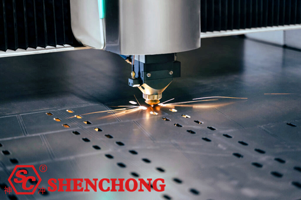
24. Process strategies for different thicknesses
0.5-2 mm thin sheets
Key focus:
- High speed
- Low heat input
- Small-hole quality
- Prevention of over-burning
- Prevention of sheet deformation
3-6 mm medium-thin sheets
This is a very common thickness range in laser cutting production.
Key focus:
- Speed
- Assist gas
- Focal position
- Small-hole quality
- Common-line cutting
8-12 mm medium-thick sheets
Focus shifts to:
- Piercing
- Gas-based slag removal
- Nozzle
- Focal position
- Gas pressure
- Cut-face perpendicularity
16-30 mm thick sheets
Key focus:
- Laser power
- Piercing capability
- Gas pressure
- Focal position
- Cutting speed
- Material quality
- Cutting head capability
When cutting thick sheets, one should not simply pursue speed; instead, prioritize:
Stability + Cut-face quality + Continuous processing capability.
25. Core methods for improving cutting efficiency
If the goal is to increase production capacity, consider the following approaches:
1) Increase laser power
Suitable for high-volume thick sheet processing.
2) Optimize cutting parameters
Avoid relying on conservative parameters for extended periods.
3) Reduce the number of piercings
Achieved through optimized nesting and common-line cutting.
4) Optimize cutting paths
Reduce non-cutting (air-cut) movement.
5) Increase acceleration
Enhance dynamic performance within the machine tool’s limits.
6) Automated loading/unloading
Reduce manual handling.
7) Automatic nesting
Improve material utilization.
8) Establish a parameter database
Reduce machine setup/testing time.
26. Integrating robotics/automated loading and unloading with laser cutting
For mass production, further integration can be achieved using:
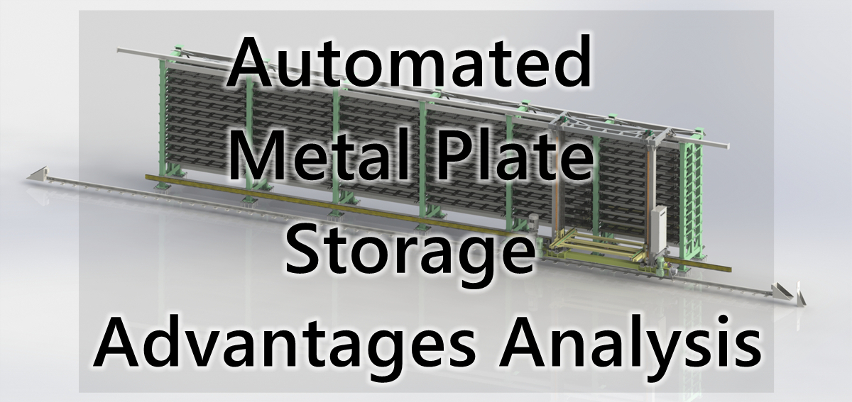
Intelligent sheet storage + Laser cutting machine + Automated loading/unloading + Finished part sorting
…to form an automated production cell.
Typical workflow:
Smart material storage → Automatic material retrieval → Laser cutting → Finished part sorting → Scrap handling → Finished part buffering
This reduces:
- Manual handling
- Waiting time
- Time spent locating materials
- Loading and unloading time
- Production errors
At the same time, it improves:
- Equipment utilization
- Personnel safety
- Production continuity
- Material utilization
For high-volume sheet metal production, this represents a key direction in the evolution of laser cutting from “standalone processing” to “smart manufacturing cells.”
27. Tips for Daily Maintenance of Laser Cutting Machines
Daily Checks
Key items to check:
- Nozzle
- Protective lens
- Gas pressure
- Chiller
- Laser head
- Sheet metal platform
- Dust removal system
Weekly Checks
Recommended checks:
- Guide rails
- Gear racks
- Transmission components
- Cables
- Gas lines
- Cooling system
- Nozzle coaxiality
- Periodic Checks
Includes:
- Laser output status
- Optical system
- Motion accuracy
- Servo system
- Automatic height adjustment system
- Coolant
- Compressed air system
Maintenance should be performed according to the equipment manufacturer’s requirements.
28. Tips for Improving Laser Cutting Precision
If high dimensional accuracy is required, considerations must be made across three areas: mechanical, software, and process.
Mechanical Aspects
Check:
- Guide rail accuracy
- Rack and pinion
- Lead screw
- Machine frame rigidity
- Crossbeam deformation
- Servo motors
Software Aspects
Check:
- CAD drawings
- CAM parameters
- Kerf compensation
- Lead-in lines
- Path planning
- Acceleration/deceleration
Process Aspects
Check:
- Sheet thickness
- Thermal deformation
- Cutting sequence
- Focal point
- Cutting speed
29. How to Improve Cut Surface Perpendicularity?
This is particularly important when cutting thick plates.
If the cut profile is wider at the top and narrower at the bottom (or vice versa), there may be an issue with the laser beam’s energy distribution along the material’s thickness.
Key areas to check:
- Focal point position
- Laser beam quality
- Nozzle coaxiality
- Assist gas
- Cutting speed
- Protective lens
- Material condition
If the problem persists, further inspection of the laser beam and the cutting head’s optical system is required.
30. Most Practical Troubleshooting Sequence for the Production Floor
When laser cutting quality suddenly drops, do not immediately make drastic changes to all parameters.
Recommended approach:
Step 1: Check the sheet material
Verify: Material type, thickness, and flatness.
Step 2: Check the nozzle
Verify: Check for deformation, clogging, or contamination.
Step 3: Check the protective lens
Verify: Check for contamination or damage.
Step 4: Check gas
Verify: gas type, pressure, purity, and flow rate.
Step 5: Check focus
Verify: correct focus position.
Step 6: Check speed
Make minor adjustments.
Step 7: Check power
Verify: normal laser output.
Step 8: Check mechanical system
If the following issues persist:
- Dimensional errors
- Deformation of circular holes
- Straight lines not straight
- Abnormal repeatability
Then further inspect:
Guide rails, gear racks, servo systems, the machine frame, and the motion control system.
31. "Golden Rules" for Laser Cutting Process Optimization
In actual production, the following principles can serve as quick diagnostic criteria:
Failure to cut through: Check speed, focus, and gas first.
Dross accumulation: Check speed, gas pressure, focus, and nozzle first.
Dross on one side: Focus on nozzle concentricity.
Non-round small holes: Check speed, acceleration, focus, and mechanical precision.
Sharp corners burning: Reduce heat input at corners.
Sheet deformation: Optimize nesting and cutting sequence.
Sudden drop in cutting quality: Check the protective lens and nozzle first.
Inability to cut thick plates: Focus on power, piercing, gas pressure, and focus.
Thin sheets prone to burning: Reduce heat input and optimize speed, power, and piercing.
32. Advanced Optimization Strategies for Sheet Metal Laser Cutting
If a company can already consistently perform standard laser cutting, the next stage is to move beyond merely “getting the cut done” to:
① Cut faster
Increase:
Cutting speed (m/min)
② Cut better
Improve:
- Roughness
- Perpendicularity
- Burrs
- Heat-affected zone (HAZ)
- Round hole precision
③ Cut more economically
Reduce:
- Oxygen consumption
- Nitrogen consumption
- Electricity consumption
- Nozzle consumption
- Lens consumption
④ Cut more reliably
Increase:
- Continuous processing time
- Piercing success rate
- Parameter repeatability
- Batch consistency
⑤ Cut intelligently
Further introduce:
Auto-focusing + Automatic nozzle changing + Automatic loading/unloading + Intelligent nesting + Intelligent warehousing + Process database + MES production management
Ultimately establishing:
Intelligent warehousing → Automatic loading → Laser cutting → Automatic sorting → Finished product buffering → Data management
…a complete intelligent sheet metal production workflow.
33. Quick Checklist for Sheet Metal Laser Cutting
Production personnel can perform checks directly in the following order:
1) Before Cutting
□ Correct sheet material
□ Correct sheet thickness
□ Sheet is flat
□ Laser unit status normal
□ Chiller functioning normally
□ Gas supply normal
□ Nozzle in good condition
□ Protective lens clean
□ Focus calibrated
□ Nozzle coaxiality normal
2) During Mtela Laser Cutting
□ Stable piercing
□ Normal spark direction
□ Stable cutting sound
□ No significant dross/slag
□ No significant edge burning
□ Stable laser head height
□ Stable gas pressure
□ No severe thermal deformation of the sheet
3) After Cutting
□ Inspect cut surface
□ Check for burrs
□ Check dimensions
□ Check hole diameters
□ Check roundness
□ Check perpendicularity
□ Record optimal parameters
□ Update process database
34. Summary: What Defines Truly High-Level Laser Cutting?
High-level sheet metal laser cutting is not simply a matter of owning a high-power laser cutting machine.
A truly excellent laser cutting process requires getting everything right across these areas:
Equipment, materials, parameters, gas, nozzles, focus, piercing, cutting paths, nesting, maintenance, and automation.
This can be summarized in a comprehensive formula:
High-quality laser cutting = Appropriate laser power + Stable beam quality + Accurate focus + Suitable nozzle + Appropriate assist gas + Precise gas pressure + Reasonable cutting speed + Excellent machine motion accuracy + Correct cutting path + Good maintenance
For modern sheet metal factories, the direction of future development is:
High-power laser cutting → High-speed cutting → Automatic loading/unloading → Intelligent nesting → Automatic sorting → Intelligent warehousing → MES/ERP data integration
This represents the core trajectory for the evolution of sheet metal laser cutting—moving from standalone machines toward intelligent, automated, and unmanned production lines.


 English
  Spanish
  Portuguese
  Russian
  Arabic
  French
  Italian
  German
  Polish
  Thai
Thai  Vietnamese
  Lithuanian
  Czech
Czech  Japanese
  Chinese