

Table of Contents
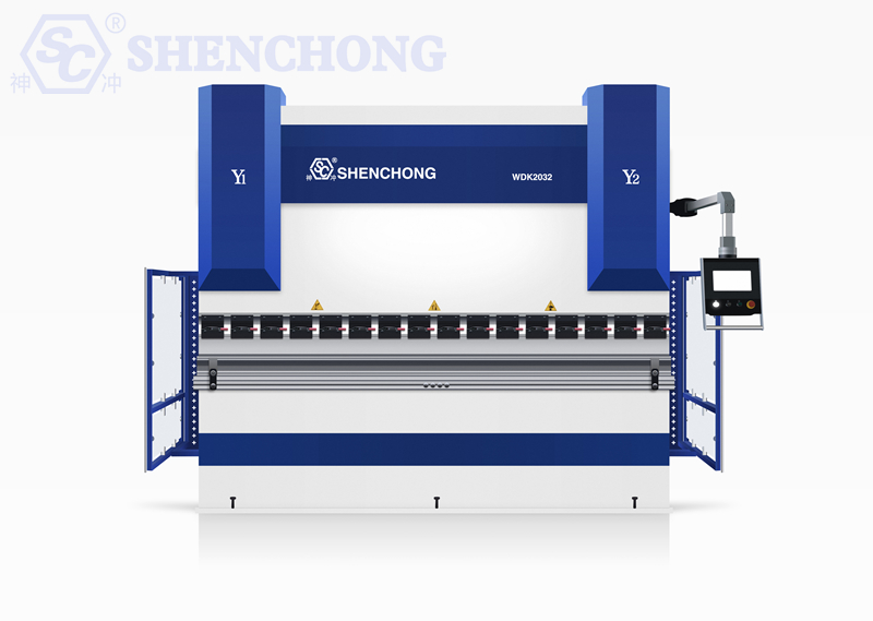
A hydraulic CNC bending machine is a sheet metal processing device that uses a hydraulic drive system to move a slide up and down, applying pressure to metal sheets through upper and lower dies to bend the sheets to a predetermined angle and size.
This manual applies to common hydraulic CNC bending machines, including ordinary CNC hydraulic bending machines, servo hydraulic bending machines, hybrid hydraulic-electric bending machines, and machines equipped with CNC systems such as ESA, DELEM, Cybelec, and SC EL.
The specific operating interface may vary between manufacturers, tonnage, number of axes, and CNC systems. Therefore, in actual operation, the electrical diagrams, hydraulic schematics, CNC system manuals, and accompanying technical documents provided by the equipment manufacturer should be consulted.
1. Essential Knowledge Operators Must Master
Before commencing operation, operators should familiarize themselves with the following:
- Equipment structure and names of major components
- Basic operating procedures of the CNC system
- Installation, adjustment, and use of bending dies
- Sheet material, thickness, and dimensions
- Relationship between bending force and equipment tonnage
- Relationship between V-groove width, sheet thickness, and bending radius
- Relationship between bending angle and springback
- Operating mode of the back gauge system
- Basic requirements of the hydraulic and lubrication systems
- Location of emergency stop button and safety protection devices
- Common alarm messages and basic handling methods
Untrained personnel are prohibited from operating the equipment independently.
2. Hydraulic CNC Bending Machine Equipment Overview
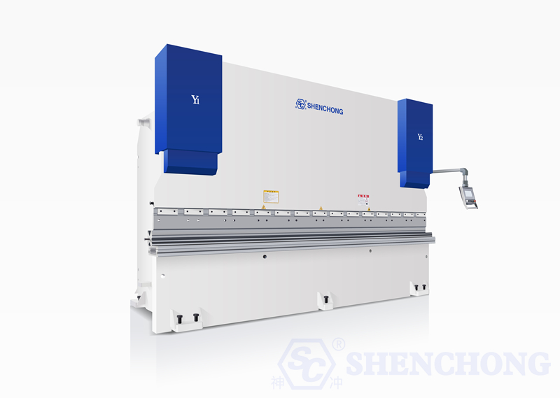
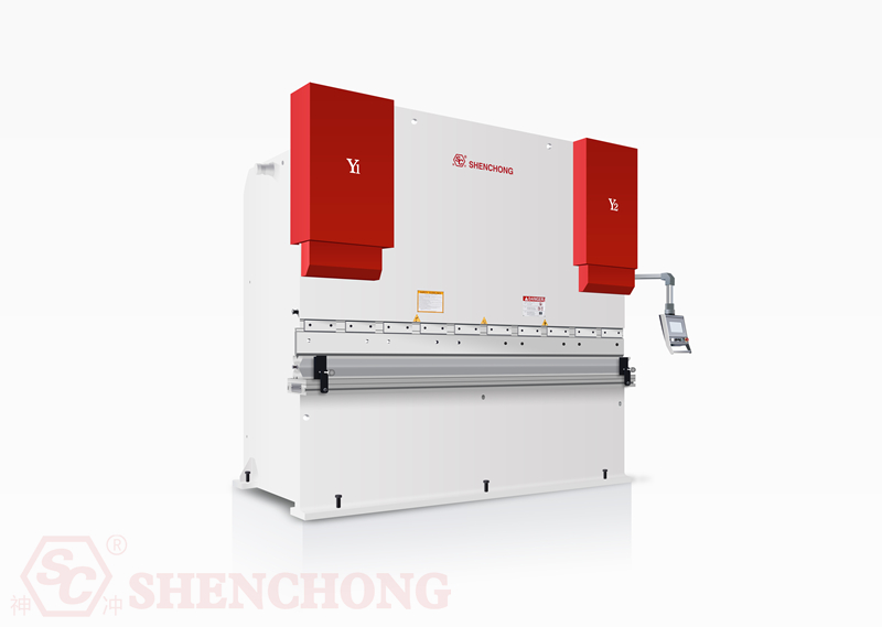
A hydraulic CNC bending machine is a sheet metal processing machine that uses a hydraulic system to drive a slide to move up and down, applying pressure to the metal sheet through upper and lower dies, causing plastic deformation and thus obtaining a specified bending angle and size.
A typical machine mainly consists of the following systems:
- Frame system
- Slide system
- Hydraulic system
- CNC system
- Back gauge system
- Die system
- Worktable and compensation system
- Electrical control system
- Safety protection system
- Lubrication system
- Foot switch and operating device
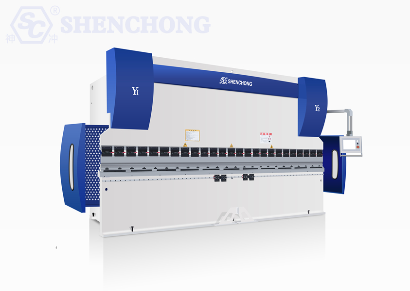
Modern CNC bending machines typically achieve functions such as Y1/Y2 axis synchronous control, X-axis back gauge control, R-axis height control, Z1/Z2 axis lateral stop control, and worktable deflection compensation.
3. Main Components Of CNC Hydraulic Press Brake
A typical hydraulic CNC bending machine mainly consists of the following parts:
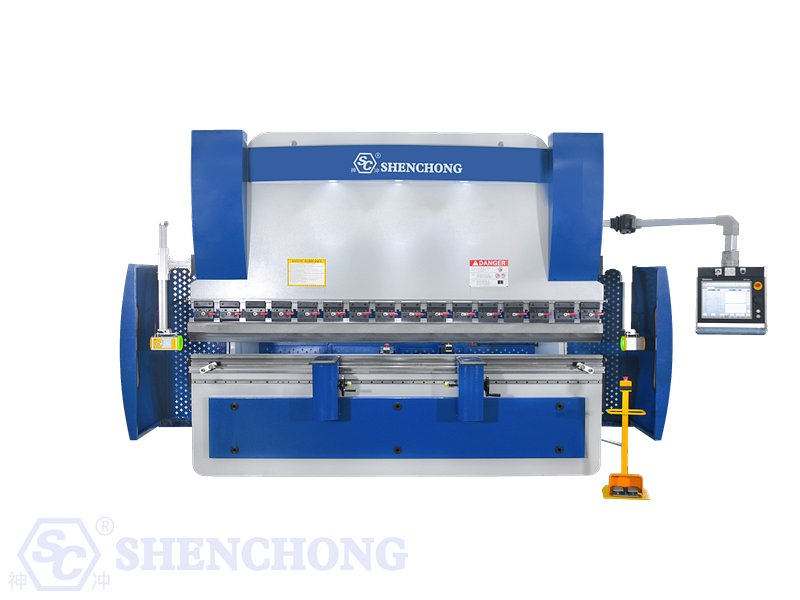
1) Frame
The frame typically consists of left and right side plates, a worktable, connecting structures, and an upper crossbeam, forming the load-bearing foundation of the entire bending machine.
Frame rigidity directly affects:
- Bending accuracy
- Bending angle consistency
- Long-term stability
- Equipment reliability under off-center loads
2) Slider
The slider holds the upper die and moves up and down under the drive of the hydraulic system.
During bending, the slider moves downwards, pressing the upper die between the sheet metal and the lower die, thus completing the bend.
3) Worktable
The worktable holds the lower die and bears the main reaction force generated during bending.
Some high-end hydraulic CNC bending machines are equipped with mechanical or hydraulic compensation systems to improve the consistency of the angle between the middle and ends during the bending of long plates.
4) Hydraulic System
A hydraulic system typically includes:
- Hydraulic pump
- Motor
- Hydraulic valve assembly
- Oil tank
- Oil pipes
- Hydraulic cylinder
- Pressure detection and control components
The hydraulic system is responsible for generating and controlling the power required for the slide movement.
5) CNC System
The CNC system is the core control unit of the equipment.
Depending on the configuration, it can achieve:
- Bending program editing
- Angle control
- Back gauge positioning
- Multi-process automatic operation
- Die parameter management
- Bending sequence calculation
- Axis position control
- Production counting
- Alarm diagnosis
- Parameter backup, etc.
6) Back gauge System
The back gauge is used to determine the bending position of the sheet metal.
Common axis configurations include:
- X-axis: Controls the back gauge’s forward and backward movement
- R-axis: Controls the up and down movement of the stop finger
- Z1/Z2 axes: Control the left and right stop finger positions
The actual axis configuration is subject to the equipment nameplate and CNC system configuration.
7) Dies
Bending dies typically include:
- Upper die
- Lower die
- V-shaped lower die
- Multi-V lower die
- Special forming dies.
The choice of mold directly affects the bending angle, inner radius, bending force, and forming quality.
4. Pre-Start Safety Inspection
A comprehensive inspection must be conducted before starting the machine. production must not be started directly.
1) Mechanical System Inspection
Inspect:
- Check for obvious deformation of the frame.
- Check for secure installation of the upper and lower dies.
- Check for cracks, chipped corners, or severe wear on the dies.
- Check for cleanliness of the worktable.
- Check for obstructions in the slide block movement area.
- Check for foreign objects in the back gauge area.
- Check for loose mechanical connection bolts.
- Check for integrity of protective devices.
2) Hydraulic System Inspection
Inspect:
- Check for normal hydraulic oil level.
- Check for ruptured oil pipes.
- Check for leaks at joints.
- Check for obvious oil leaks in the hydraulic cylinders.
- Check for abnormal noises from the hydraulic station.
- Check for hydraulic oil temperature within the allowable range.
- If serious oil leaks are found, the equipment must not be operated.
3) Electrical System Inspection
Inspect:
- Whether the power supply voltage meets equipment requirements.
- Whether the electrical cabinet is normal.
- Whether the grounding is reliable.
- Whether the cables are damaged.
- Whether the control panel is normal.
- Whether the emergency stop button is in the released state.
- Whether safety light curtains and other protective devices are normal.
4) Working Environment Inspection
The following must not be piled up around the equipment:
- Scrap sheet metal
- Tools
- Oil drums
- Cables
- Flammable materials
- Miscellaneous items unrelated to production.
The operating area should maintain sufficient lighting and passage space.
5. Correct Start-up Procedure
A typical hydraulic CNC bending machine can be started up in the following sequence:
Step 1: Connect Main Power
Turn on the main power supply of the equipment.
Observe whether the electrical cabinet, control system, and related indicator lights are normal.
Step 2: Start CNC System
Start the CNC controller and wait for the system to complete initialization.
Do not operate other functions during system startup.
Step 3: Release Emergency Stop
After confirming that there are no people or obstacles around the equipment, release the emergency stop button.
Step 4: Start Hydraulic System
Press the hydraulic pump start button.
Observe whether the hydraulic system exhibits:
- Abnormal noise
- Severe vibration
- Oil leakage
- Abnormal pressure
- Alarm messages
Step 5: Equipment Return to Reference Point
Some CNC press brake bending machines require a return-to-reference-point operation after startup.
Follow the prompts of the CNC system to establish the correct mechanical position reference for each control axis.
Step 6: No-load Run Inspection
Perform a low-risk no-load run without any sheet metal to check:
- Slider up-and-down movement
- Back gauge movement
- Axis positioning
- CNC system display
- Safety protection devices
Production can only begin after confirming everything is normal.
6. Sheet Material Preparation Before Bending
Bending quality depends not only on the bending machine but also on the sheet material itself.
Before processing, the following should be confirmed:
1) Material
Common materials include:
- Q235 carbon steel
- Q355 high-strength steel
- Stainless steel
- Aluminum plate
- Copper plate
- Galvanized plate, etc.
Different materials have different yield strengths and springback characteristics.
1) Material
Common materials include:
- Q235 carbon steel
- Q355 high-strength steel
- Stainless steel
- Aluminum plate
- Copper plate
- Galvanized plate, etc.
Different materials have different yield strengths and springback characteristics.
2) Sheet Material Thickness
The actual sheet thickness must be confirmed; it cannot rely solely on the material label.
For example, a sheet material nominally 3 mm may have a certain tolerance in its actual thickness.
3) Sheet Material Length
Confirm that the sheet material length matches the effective working length of the bending machine and the process requirements.
4) Sheet Material Surface
Inspect for:
- Scratches
- Rust
- Burnt burrs
- Weld slag
- Oil stains
- Oxide scale
For workpieces with high decorative value, protective films, soft pads, etc., should be used to reduce die indentations.
7. Bending Die Selection
Die selection is a crucial step in bending operations.
1) Selecting the Lower Die V-groove Based on Plate Thickness
Generally, a wider V-groove results in a larger inner radius (R) during bending, which in turn changes the required bending force.
Actual V-groove selection must comprehensively consider:
- Plate Thickness
- Material
- Bending Radius
- Bending Angle
- Bending Force
- Die Allowable Load
It cannot be simply assumed that “the larger the V-groove, the better.”
2) Upper Die Selection
Select based on workpiece structure:
- Standard Straight Die
- Pointed Die
- Eagle Beak Die
- Gooseneck Die
- Segmented Die
- Special Forming Die
For workpieces such as boxes, deep grooves, and U-shaped parts, special attention should be paid to whether the upper die will interfere with the workpiece.
8. Die Installation Operation
1) Before Installation
Turn off unnecessary motion functions and ensure the equipment is in a safe state.
Clean:
- Upper Die Clamping Area
- Lower Die Installation Area
- Die Contact Surface
2) Installing the Upper Die
Correctly install the upper die into the upper die fixture.
Inspection:
- Die direction
- Die length
- Die locking status
- Die height
- Die segment position
3) Install the lower die
Install the lower die on the worktable.
Check if the lower die is:
- Stable placement
- Reliable locking
- V-groove direction consistent
- Correct connection of each segment
4) Die alignment
After installation, check if the center lines of the upper and lower dies are aligned.
High-pressure bending is prohibited if the die is not properly aligned.
9. Bending Program Settings
Hydraulic CNC bending machines typically employ a programmed production method.
A complete bending program usually includes:
- Material parameters
- Slab thickness
- Workpiece length
- Bending angle
- Bending radius
- Die information
- Back gauge position
- Bending sequence
- Motion parameters for each axis
- Pressure or bending force
- Speedparameters
- Compensation parameters
10. Bending Angle Settings
For example, to process a workpiece with a 90° bend.
The target angle should be entered in the program.
However, please note:
The angle definition displayed by the CNC system must be consistent with the specific system.
Different systems may have different definitions for angles, interior angles, exterior angles, and coordinate directions. Therefore, a trial bend should be performed when using a new system or program for the first time.
11. Back Gauge Settings
The back gauge is a crucial mechanism for controlling bending dimensions.
During operation:
- Input target dimension
- System calculates corresponding axis position
- Back gauge moves automatically
- Operator checks actual position
- Place sheet metal
- Make sheet metal fit tightly against the stop finger
- Perform bending
For complex workpieces, different stop positions should be set according to the bending sequence.
12. Trial Bending Operation
A trial bending operation must be performed before formal mass production.
Recommended procedure:
Program Input → Dry Run → Single-piece Trial Bending → Dimension Inspection → Angle Inspection → Parameter Correction → First-piece Confirmation → Mass Production
Key points to check during trial bending:
- Bending angle
- Bending length
- Relationship between hole position and bending line
- Inner radius
- Appearance
- Surface indentation
- Dimensional relationship between multiple bends.
13. Standard Bending Operation Procedure
The following procedure can be followed during formal production:
1) Read the drawing
Confirm:
- Material
- Thickness
- Total length
- Bending dimension
- Bending angle
- Bending direction
- Quantity
- Appearance requirements
2) Check the program
Confirm that the program is consistent with the current workpiece.
3) Check the mold
Confirm that the mold model is consistent with the program.
4) Place the sheet metal
Place the sheet metal stably on the worktable.
5) Align the back gauge
Make the reference edge of the sheet metal contact the back gauge.
6) Initiate Bending
Operate the machine using the hand or foot control devices according to the equipment design requirements.
7) Complete Bending
The slider returns to the safe position.
8) Remove the Workpiece
Use appropriate handling methods based on the workpiece’s weight and dimensions.
9) Inspection
Check dimensions and angles.
10) Mass Production
Mass production begins only after the first piece is confirmed to bequalified.
14. Precautions During Bending
1) Overloading is Strictly Prohibited
The bending force must not exceed the equipment’s rated capacity.
Especially note: The tonnage of a bending machine does not mean that it can be used for any length, any material, or any V-groove.
Bending force is related to the following factors:
- Material strength
- Sheet thickness
- Bending length
- Lower die V-groove
- Bending method
- Bending radius
2) Avoid Uneven Loading
Long workpieces should have their force distributed as reasonably as possible.
Severe uneven loading may lead to:
- Die damage
- Abnormal slider force
- Worktable deformation
- Decrease in equipment accuracy
3) Hands Must Not Be Placed in Dangerous Areas
During slider movement, it is strictly forbidden to place hands, fingers, or other body parts between the upper and lower dies.
4) Touching Moving Parts is Prohibited
During equipment operation, the following must not be touched:
- Slider
- Back gauge
- Die
- Hydraulic cylinder
- Coupling
- Other moving parts
15. Handling Bending Springback
Metal sheets typically exhibit a certain degree of springback after bending.
For example, if the target angle is 90°, the material may spring back to 92° or other angles after pressure is released.
The degree of springback is related to:
- Material type
- Material strength
- Sheet thickness
- Bending radius
- V-groove width
- Bending method
Common adjustment methods:
These can be achieved by:
- Modifying the bending angle.
- Adjusting the bending depth.
- Adding compensation.
- Modifying the mold.
- Changing the V-groove.
- Optimizing the bending sequenc.
- Improving the final angle.
In actual production, stable process parameters should be established based on trial bending results.
16. Bending Quality Inspection
Quality inspection should be performed on both the first piece and batch products.
1) Dimensional Inspection
Used:
Vernier calipers, steel ruler, depth gauge, height gauge, coordinate measuring machine, special inspection tools. Inspect critical dimensions.
2) Angle Inspection
Used:
Electronic angle gauge, digital angle meter, angle gauge, special inspection tools.
3) Visual Inspection
Inspect:
Cracks, indentations, scratches, deformation, burrs, mold marks, surface damage.
17. Common Bending Defects and Solutions
Reference Table:
Problems | Possible causes | Solutions |
Bending angle too large | Excessive springback | Increase bending depth or perform angle compensation |
Bending angle too small | Excessive compression | Reducing downward pressure |
Inconsistent left and right angles | Abnormal stress or compensation | Inspecting the frame, die, and compensation system |
Incorrect bending dimensions | Incorrect back gauge position | Inspecting the X-axis and stop |
Indented marks on workpiece | Unsuitable mold | Replacing with a suitable die or implementing protective measures |
Cracked workpiece | Insufficient radius or unsuitable material | Increasing the radius (R-angle) or adjusting the process |
Twisted workpiece | Uneven material, mold, or stress | Adjusting the die and bending sequence |
Gradually deviating dimensions after multiple bends | Inappropriate process sequence or positioning method | Optimizing the bending sequence |
Unstable back gauge positioning | Machinery clearance or abnormal drive | Inspecting the transmission system and shaft parameters |
Abnormal slider operation | Hydraulic system malfunction | Inspecting the hydraulic oil, valve assembly, pump, and sensors |
18. CNC System Operation Precautions
When operating the CNC system, the following parameters must not be modified arbitrarily:
- Machine tool parameters
- Axis parameters
- Servo parameters
- Hydraulic parameters
- Pressure parameters
- Encoder parameters
- Safety parameters
- Manufacturer calibration parameters.
These parameters directly affect equipment accuracy and safety.
If modifications are necessary, they should be performed by trained technicians, and parameters should be backed up beforehand.
19. Shutdown Procedure
After normal production is completed, the hydraulic cnc bending machine should be shut down according to the prescribed procedure.
Recommended Procedure:
- Complete the current workpiece
- Return the slide to the safe position
- Move the back gauge to the safe position
- Clean the worktable
- Clean the mold and surrounding area
- Save the production program
- Stop the hydraulic system
- Turn off the CNC system
- Turn off the main power supply
- Record equipment usage
- Maintain a record of equipment usage
After equipment shutdown, check for the following:
- Oil leakage
- Abnormal temperature rise
- Unusual noise
- Alarm
- Mold damage
- Electrical abnormality
20. Daily Maintenance
1) Daily Maintenance
It is recommended to check daily:
- Hydraulic oil level
- Oil pipes and connectors
- Mold condition
- Back gauge
- Worktable
- Lubrication points
- Emergency stop device
- Safety protection devices
- CNC system alarms
2) Weekly Maintenance
Check:
- Mold clamping mechanism
- Bolt connections
- Back gauge transmission components
- Guide rails
- Electrical cabinet
- Fan and filter device
- Hydraulic system operating status
3) Monthly Maintenance
Check:
- Hydraulic oil condition
- Hydraulic pipelines
- Electrical wiring
- Mechanical connections
- Guide rail lubrication
- Transmission system
- Position detection elements
- Compensation mechanism
4) Periodic Maintenance
Perform according to the equipment manufacturer’s specified cycle:
- Hydraulic oil testing or replacement
- Filter element replacement
- Lubricating oil replenishment
- Electrical system inspection
- Hydraulic system pressure check
- Accuracy testing
- Axis positioning accuracy testing
21. Hydraulic System Maintenance
The hydraulic system is one of the core power systems of a hydraulic CNC bending machine.
Maintenance focuses include:
1) Hydraulic Oil
Use the hydraulic oil specified by the manufacturer.
Different hydraulic oils must not be mixed arbitrarily.
2) Oil Cleanliness
The hydraulic system is sensitive to contaminants.
Oil contamination may lead to:
- Valve core jamming
- Pump wear
- Unstable pressure
- Abnormal slider movement
- Reduced system lifespan
3) Regular Leak Checks
If oil leaks are found in oil pipes, joints, or hydraulic cylinders, they should be dealt with promptly.
Never check for high-pressure oil leaks by hand.
22. Lubrication Maintenance
Lubrication should be performed at the specified lubrication points according to the equipment manual.
Common lubrication points include:
- Guide rails
- Mechanical transmission mechanism
- Back gauge screw
- Bearings
- Die-related moving mechanisms.
More lubrication is not necessarily better. Excessive lubrication may attract dust, forming contaminants and accelerating wear.
23. Common Alarm Handling Procedures
When an alarm occurs, do not immediately and repeatedly restart the hydraulic cnc bending machine.
It is recommended to follow these steps:
Read the alarm → Determine the alarm type → Inspect the site → Eliminate obvious causes → Reset → Low-speed test → Resume production
1) Servo Alarm
Key checks:
- Motor
- Driver
- Encoder
- Cable
- Mechanical resistance
- Axis movement obstructed
2) Hydraulic Alarm
Check:
- Hydraulic oil level
- Oil temperature
- Hydraulic pressure
- Pump
- Valve group
- Pressure sensor
3) Safety Alarm
Check:
- Emergency stop
- Safety light curtain
- Protective door
- Safety relay
- Foot switch
- Safety circuit
Safety protection should not be forcibly deactivated before the cause of a safety alarm is identified.
24. Emergency Shutdown
The equipment should be stopped immediately if any of the following occurs:
- Abnormal and severe vibration of the equipment
- Severe oil leakage
- Abnormal loud noise
- A clear crack in the mold
- Workpiece dangerously stuck
- Personnel entering a dangerous area
- Smoke or odor from the electrical system
- Abnormally high hydraulic system pressure
- Safety device malfunction
Press the emergency stop button immediately. Disconnect the main power supply to the equipment if necessary. Do not restart the machine before the cause of the accident is determined.
25. Personnel Safety Requirements
Operators must comply with the following basic safety regulations:
- Wear work clothes that meet workshop requirements.
- Use necessary personal protective equipment.
- Do not wear loose ornaments that could easily get caught in the equipment.
- Do not perform maintenance while the equipment is running.
- Do not cross over moving parts.
- Do not place hands or tools between dies.
- Do not turn off safety protection devices without authorization.
- Do not overload the machine.
- Do not use dies with cracks or serious damage.
- Do not allow untrained personnel to operate the equipment.
26. Ten Prohibitions Safe Operation Of Bending Machines
- Do not overload the hydraulic cnc bending
- Do not use damaged dies.
- Do not process under severe uneven load.
- Do not put your hands between the upper and lower dies.
- Do not perform maintenance while the equipment is running.
- Do not turn off safety protection devices without authorization.
- Do not arbitrarily modify core system parameters.
- Do not pile up debris around the equipment.
- Do not operate the equipment independently without training.
- Do not force production when the cause of the malfunction is unknown.
27. Operational Techniques To Improve Bending Accuracy
1) Careful First-Piece Measurement is Essential
Don’t assume that a correct CNC program guarantees a qualified product.
First-piece measurement is a crucial step in stable mass production.
2) Maintain Material Consistency as Much as Possible
Use sheet metal of the same batch of products with:
- Same material
- Same thickness
- Similar mechanical properties
3) Keep Dies in Good Condition
Wearing dies will affect:
- Bending angle
- Inner radius (R)
- Dimensions
- Surface quality
4) Optimize Bending Sequence
For complex workpieces, the bending sequence should be arranged reasonably to avoid:
- Interference
- Collision
- Difficulty in positioning
- Workpiece deformation
- Inability to position subsequent bends
5) Utilize Compensation Appropriately
For long workpieces, mechanical or hydraulic compensation functions can be used depending on the equipment configuration to improve the consistency of angles along the entire length.
28. Bending Precautions for Different Materials
1) Q235 Carbon Steel
Q235 carbon steel sheet has good formability and is a common bending material.
Key considerations:
- Sheet thickness
- V-groove
- Bending radius
- Springback
2) Stainless Steel
Generally exhibits more pronounced springback and higher formability requirements than ordinary carbon steel.
Special attention should be paid during processing:
- Die selection
- Bending force
- Surface protection
- Springback compensation
- Minimum bending radius
3) Aluminum Sheet
Aluminum sheet is relatively soft, but different grades have significantly different properties.
Consider:
- Surface scratches
- Cracks
- Die indentations
- Material orientation
4) High-Strength Steel
High-strength steel requires greater bending force, and springback is usually more pronounced.
Equipment capacity and process parameters must be recalculated based on the actual strength of the material.
29. Bending Force Estimation
The actual bending force of a V-bend is related to factors such as the material’s tensile strength, plate thickness, bending length, and V-groove width.
In engineering practice, the bending force can be estimated using appropriate bending force calculation formulas.
Typically, the following formula can be used:
F ≈ C × σ × L × t² / V
Where:
F—Bending force
σ—Material strength parameter
L—Bending length
t—Plate thickness
V—Width of the lower die V-groove
C—Coefficient related to the bending method and unit.
In actual production, the ability of the equipment to process the bend cannot be determined solely based on empirical formulas.
For critical operating conditions, the bending force table provided by the press brake manufacturer should be used for confirmation.
30. Summary of Standard Operating Procedures for a Bending Machine
The entire production process can be summarized as follows:
Start-up Inspection
↓
Start the CNC System
↓
Start the Hydraulic System
↓
Return to Reference Point
↓
Check the Die
↓
Input/Recall the Program
↓
Check the Backgauge
↓
No-load Run
↓
Place the Sheet Metal
↓
First Piece Trial Bending
↓
Dimension and Angle Inspection
↓
Parameter Correction
↓
First Piece Confirmation
↓
Batch Production
↓
In-process Spot Check
↓
Production End
↓
Equipment Cleaning
↓
Shutdown
↓
Maintenance Record
31. Daily Inspection Checklist for Operators
Inspection Items | Inspection Items | State |
Power Supply | Voltage and power supply normal | □ |
Emergency Stop | Functional operation normal | □ |
Safety Devices | Light grating/protective device normal | □ |
Hydraulic Oil | Liquid level normal | □ |
Hydraulic System | No obvious oil leakage | □ |
Hydraulic Pump | No abnormal noise | □ |
Mold | No cracks or severe wear | □ |
Workbench | Clean and free of foreign objects | □ |
Backgauge | Normal operation | □ |
CNC System | No abnormal alarms | □ |
Guide Rails | Normal lubrication | □ |
Electrical Cabinet | No abnormal heating or odor | □ |
32. Precautions for Long-Term Equipment Shutdown
If the equipment is to be shut down for an extended period, necessary protective measures should be taken.
These include:
- Cleaning the equipment
- Cleaning the molds
- Applying rust prevention treatment
- Checking the hydraulic oil
- Checking the electrical cabinet
- Preventing moisture
- Preventing dust from entering
- Regularly checking the equipment status.
When restarting, do not immediately begin full-load production. A comprehensive inspection, power-on test, low-speed operation, and no-load operation should be performed first.
33. Operator Training Recommendations
New operators are recommended to be trained in the following stages:
Stage 1: Safety Training
Master:
- Emergency stop
- Safety areas
- Danger areas of the molds
- Safety devices
- Emergency handling
Stage 2: Equipment Familiarization
Understand:
- Frame
- Slider
- Worktable
- Hydraulic system
- Back gauge
- CNC system
- Molds
Stage 3: Basic Operation
Learn:
- Powering on
- Returning to zero
- Program call
- Parameter input
- Back gauge operation
- Single-step operation
Stage 4: Actual Bending
Completed under the guidance of experienced personnel:
- Die installation
- Sheet material positioning
- First piece trial bending
- Dimensional inspection
- Parameter correction
Stage 5: Independent Production
Independent operation is only permitted after passing an assessment.
34. Conclusion
The correct operation of a hydraulic CNC bending machine is not simply a matter of “inputting the angle, placing the sheet material, and pressing the switch.”
Truly stable and efficient bending production requires integrating equipment, dies, materials, programs, positioning, bending force, springback compensation, bending sequence, quality inspection, and equipment maintenance.
In actual production, it is recommended to establish a standardized management process:
“Equipment Inspection → Process Preparation → Program Verification → Die Confirmation → First Piece Trial Bending → First Piece Inspection → Mass Production → In-Process Sampling Inspection → Equipment Maintenance”
For equipment equipped with multi-axis CNC systems, automatic compensation, servo back gauge, robot loading and unloading, or automatic bending units, corresponding CNC system operation, automation operation, mold management, fault diagnosis, and maintenance sections should be added to this basic manual to form a complete internal “Hydraulic CNC Bending Machine Operation and Maintenance Manual”.


 English
  Spanish
  Portuguese
  Russian
  Arabic
  French
  Italian
  German
  Polish
  Thai
Thai  Vietnamese
  Lithuanian
  Czech
Czech  Korean
  Japanese
  Chinese